MODELLING and SCULPTING
Meet the Experts: Pixar Animation Studios, The OpenSubdiv Project
The Art of Anatomy: Sculpting and Rendering Techniques for Creating a Lifelike 3D Model
Tyler, The Creator (Realtime Character Modeling/Rendering)
Two dimensional is having width and height but no depth.
Three dimensional is having width, height and depth like a solid object.
Blender is a professional, free and open-source 3D computer graphics softwaretoolset used for creating animated films, visual effects, art, 3D printed models, interactive 3D applications and video games. Blender’s features include 3D modeling, UV unwrapping, texturing, raster graphics editing, rigging and skinning, fluid and smoke simulation, particle simulation, soft body simulation, sculpting, animating, match moving, camera tracking, rendering, motion graphics, video editing and compositing. It further features an integrated game engine.
Bryce is a 3D modeling, rendering and animation program specializing in fractal landscapes. The name is taken from Bryce Canyon—a rugged region with many of the same landscapes that were first simulated with the software.
Carrara is a full-featured 3D computer graphics application featuring figure posing and editing, as well as nature modeling, in addition to traditional modeling, animation, texturing and rendering. The software is also capable of dynamic hair and fur simulations, particle effects, soft body and rigid body dynamics. Carrara is now owned and developed by DAZ 3D. Carrara is compatible with Poser and DAZ format 3D figures and props. It is further supported by a number of 3rd party plug-ins and add-ons.
Daz Productions, Inc., commonly known as Daz 3D, is a 3D content and software company specializing in providing rigged 3D human models, associated accessory content and software to the prosumer market. It was originally part of Zygote Media Group, a general purpose, application-agnostic 3D content broker, and split off as “Digital Art Zone” in 2000 to focus on supplying content for the Poser market.
Hexagon is a subdivision modeler owned by DAZ 3D. It was originally developed and published by Eovia and was acquired shortly before the release of version 2.0 by DAZ in 2006. The software drew heavily on Eovia’s other modeler, Amapi(it shared the same developers), though it omitted the NURBs and precision measuring tools. The main focus is Subdivision modeling but it includes Spline tools and surface tools. Because of the two omissions, it is not as well suited to product design as Amapi, but is aimed more at illustrative and character modeling with an eye to making it accessible for those new to working in 3D.
LightWave 3D is a 3D computer graphics software developed by NewTek. It has been used in film, television, motion graphics, digital matte painting, visual effects, video games development, product design, architectural visualizations, virtual production, music videos, pre-visualizations and advertising.
Makehuman is an open source 3D computer graphics software middleware designed for the prototyping of photo realistic humanoids. It is developed by a community of programmers, artists, and academics interested in 3D modeling of characters.
Maya /ˈmɑːjə/, commonly shortened to Maya, is a 3D computer graphics software that runs on Windows, macOS and Linux, originally developed by Alias Systems Corporation (formerly Alias|Wavefront) and currently owned and developed by Autodesk, Inc. It is used to create interactive 3D applications, including video games, animated film, TV series, or visual effects.
Maya LT modelling and animation software is built for professional indie game makers. Bring creations to life with powerful game development tools.
MeshLab is an advanced 3D mesh processing software system that is oriented to the management and processing of unstructured large meshes and provides a set of tools for editing, cleaning, healing, inspecting, rendering, and converting these kinds of meshes. MeshLab is free and open-source software, subject to the requirements of the GNU General Public License (GPL), version 2 or later, and is used as both a complete package and a library powering other software. It is well known in the more technical fields of 3D development and data handling.
Modo (stylized as MODO, originally modo) is a polygon and subdivision surfacemodeling, sculpting, 3D painting, animation and rendering package developed by Luxology, LLC, which is now merged with and known as Foundry. The program incorporates features such as n-gons and edge weighting, and runs on Microsoft Windows, Linux and macOS platforms.
Modo indie packs powerful, industry-leading 3D modeling, sculpting, and animation tools into an affordable package that’s perfect for developers and freelance game artists.
OpenSubdiv is a set of open source libraries that implement high performance subdivision surface (subdiv) evaluation on massively parallel CPU and GPU architectures. This code path is optimized for drawing deforming surfaces with static topology at interactive framerates.
Onyx Computing located in Cambridge, Massachusetts, USA, is a software development studio specializing in the design and development of knowledge based systems for procedural modeling of vegetation. The company was founded and incorporated in 1992 by Dr. Bojana Bosanac and Pjer Zanchi.
Photogrammetry is the art, science, and technology of obtaining reliable information about physical objects and the environment through processes of recording, measuring, and interpreting photographic images and patterns of recorded radiant electromagnetic energy and other phenomena (Wolf and Dewitt, 2000; McGlone, 2004).
Poser is a 3D computer graphics program optimized for 3D modeling of human figures. The program has gained popularity due to allowing beginners to produce basic animations and digital images, and the extensive availability of third-party digital models. Originally designed for illustrators.
Rhinoceros (typically abbreviated Rhino, or Rhino3D) is a commercial 3D computer graphics and computer-aided design (CAD) application software developed by Robert McNeel & Associates; an American, privately held, employee-owned company, that was founded in 1980. Rhinoceros geometry is based on the NURBS mathematical model, which focuses on producing mathematically precise representation of curves and freeform surfaces in computer graphics (as opposed to polygon mesh-based applications).
Shade 3D On January 1, 2019, Shade3D Co., Ltd. was merged into FORUM8 Co., Ltd. Shade 3D Professional is the ultimate tool for 3D modeling, rendering and animation. Shade 3D Professional contains all the features included in Shade 3D Standard plus many more. Shade 3D is a 3D modeling, rendering, animation, 3D printing computer program was developed by e frontier Japan and published by Mirye Software. From 2013 October, Shade 3D development team formed a new company called Shade3D Co.,Ltd. and continue to develop and market the program. After terminated the sales agreement with e frontier Japan and Mirye Software by the end of December 2014, Shade3D company is now developing and marketing Shade 3D products in Japan and worldwide exclusively.
Silo is a polygon/subdivision surfaces 3D modeling application created by Nevercenter. It has a focus on quick editing, a customizable interface (all mouse buttons and keyboard shortcuts can be assigned to any function), and a flexible workflow.
Terragen is a scenery generator program for Microsoft Windows and Mac OS Xdeveloped and published by Planetside Software. It can be used to create renderings and animations of landscapes.
3D-Coat is a commercial digital sculpting program from Pilgway designed to create free-form organic and hard surfaced 3D models from scratch, with tools which enable users to sculpt, add polygonal topology (automatically or manually), create UV maps (automatically or manually), texture the resulting models with natural painting tools, and render static images or animated “turntable” movies.
TopoGun is a stand-alone resurfacing, and maps baking application. The resurfacing functions in TopoGun will help you modify and/or recreate the edgeflow of your digital 3D models. The maps baking functions, will help you bake various types of texture maps from your high resolution 3D models and then allow you to apply them to your newly created optimized meshes. These texture maps contain information that will help you recover the appearance and features of the original high resolution mesh.
Transpose Master is designed to help you pose a model that is composed of SubTools. It works by creating a low resolution combined mesh of all the SubTools which you can pose. The pose can then be transferred back to the original model. The Transpose Master sub-palette is in the Zplugin palette.
Vue is a 3D scenery generator software package. It is used for the creation, animation, and rendering of natural 3D environments, in particular outdoor landscapes. It is used by visual effects studios for this purpose. For example, Industrial Light & Magic used it to make backgrounds for the movies Indiana Jones and the Crystal Skull and Pirates of the Caribbean: Dead Man’s Chest, and DreamWorks Animation used it in the 2008 film Kung Fu Panda.
Wings 3D is a free and open source subdivision modeler inspired by Nendo and Mirai from Izware. Wings 3D is named after the winged-edge data structure it uses internally to store coordinate and adjacency data, and is commonly referred to by its users simply as Wings.
WorldBuilder Pro a stand-alone scene builder and renderer for laying out and rendering 3D outdoor environments. WorldBuilder is still one of the only commercial products that allows users to render scenes that could be millions of polygons.
ZBrush is a digital sculpting tool that combines 3D/2.5D modeling, texturing and painting. It uses a proprietary “pixol” technology (see below) which stores lighting, color, material, and depth information for all objects on the screen. The main difference between ZBrush and more traditional modeling packages is that it is more akin to sculpting.
Creating Digital Humans with REBLIKA and Mao Lin Liao
Beginner’s Guide to Anatomy Basics and Character Design
3D Modeling Reel
Career Advice: Working as a Character Modeler and Facial Rigger at a Creative Studio
RETOPOLOGIZING PROGRAMS: 3D Coat, Topogun, Zremesher, Froretopo Maya, H15, MeshLab which is open source
Properly modelled base mesh>hand off to rigging>high-res details sculpted on top of the base mesh>displacement maps baked out>surfacing creates shaders incorporating displacement maps> render time sub division recreates your high res sculpt. Keeps the rig light and usable.
Animators generally don’t like displacement since you can’t see what you’re doing very well and it’s tough to animate the correctives etc get real time feedback. Most large productions doing the realistic stuff have very dense animation base meshes that handle a lot of the wrinkles, like 120k + for heads alone. Problem with a proper Zbrush sculpt is they can be gigabytes large. Multiply that by thousands of frames and you’ve got real issues. Animation is literally a 4th dimension, there’s a huge difference in complexity that Maya has to handle in comparison to ZBrush.
How is the character going to move? Will it be realistic or cartoon-like? What will be the range of motion? What kinds of expressions? How does the surface flow in the models and movements of the characters?
Adding realistic, natural movement to a model needs to consider the movement of joints and how this movement will affect the overlying muscles. Understanding the flow of the muscles and to analyse and divide up the surface accordingly directly affects the character’s movement and induces natural transformations in the skin.
What we see is the overlying skin, not the muscle and need to understand how the skin moves in relation to the structure and movement of the underlying muscles.
Look at how the surface is divided depending on the muscle, starting with the main muscle looking at how the surfaces are divided to fit the flow of the muscle. Consider sketching to show how the surfaces will be divided to fit the flow of the muscles and how the surface moves as a result of the joint.
- Mentor Insight Jonathan Rush, Lead Character artist at Battlecry Studios
- CHARACTER MODELING IN ANIMATION, WITH SHANNON THOMAS
- ARTIST INSIGHT: CALEB NEFZEN (DAVID MOLINA)
- Level up Environments with Gaea
- SCULPTING THE PERFECT DIGITAL DINO, WITH RAUL RAMOS
- ZBrush 2020
- Zbrush Character Modeling by Rafael Grassetti
- Sr. Cinematic Modeler: Jamir Blanco
- Museums at your fingertips
- Tutorial — Rafael Mustaine’s “Drake Soldier”
- APPROACHING AN ASSET FOR HIGH END FILM PRODUCTION, WITH ANDREW HODGSON
THE ROOKIES
- 26 Top Rated Vehicle projects for all you Revheads
- 3D Sculpting Fundamentals: The Making of Maestro Phoenix
- 3D Sculpting a Dark Fantasy Character Using Maya, ZBrush and Substance 3D Painter
- A Coraline Inspired Character for Meet Mat 4 Using Substance 3D Painter and Maya
- Achieving Realism in 3D Portraits Using ZBrush and Substance Painter
- Achieving Realistic Skin Details With Manual Sculpting in Zbrush
- Adrián Valiente – 3D Character & Surfacing Artist Reel 2024/2025
- The Art of Anatomy: Sculpting and Rendering Techniques for Creating a Lifelike 3D Model
- Barracuda, Zbrush Sculpt
- Building a Modular Environment Using Unreal Engine and Adobe Substance 3D
- Building a Mad Max Inspired Vehicle Using 3ds Max, Substance 3D Painter and Unreal Engine 5
- Career Advice – Working as a Character Modeler by Ian Spriggs
- Creating Advanced Character Structures for Unreal Engine 5
- Creating a Fantasy Castle in Unreal Engine
- Creating Jinx from Arcane: League of Legends
- Creating a Real Time Dark Fantasy Character for Unreal Engine
- Creating a Stylised Post-Apocalyptic Character Using ZBrush and Blender
- Creating a Stylised Bust From a 2D Concept Art
- Creating “Tonowari” from “Avatar: The Way of Water”
- Creature Concept Sculpting in ZBrush
- Designing From the Shadows: Bringing The Penguin to Life in 3D
- fantasy creature
- Film-Ready Creatures: Modeling, Topology & Texturing Tips
- Foraging Honey Bee | Environment
- Free 3D Model: Kombi Vanf
- Free Character Animation FX Scene
- Free 3D Model: Eddie Robot
- Geralt of Rivia / Manticore Armor (Sculpt)
- Getting Started with 3D Prop Modeling
- Gunpla Unit Gigantis
- Hippo Anatomy Study: Demystifying Skeleton and Muscle Sculpting
- How To Create Photo Realistic Characters in 3D in Autodesk Maya
- How to Create a Realistic Fish Model Using Substance 3D Designer and Mari
- How to Create a 3D Character: The Making Of Rabari Woman
- How to Build & Light a 3D Environment
- How Do You Become an Arch-viz Modelling Artist?
- How to Create World of Warcraft Characters using ZBrush – Part 1
- How to Create World of Warcraft Characters using ZBrush – Part 2
- Interactive Costume Design: Reimagining Movie Wardrobes with Digital Fashion
- Learn How to Create Chappie’s BustOswyn “The lone wolf”
- Modeling and Rigging a Quadruped Model Using Maya and ZBrush
- Modeling, Texturing and Rendering a 3D Warlock Character
- Mystifell Street
- Photorealistic 3d Character Design Process – Mursi Tribe Portrait
- Step-by-Step 3D Character Workflow Using Blender and Substance 3D for Beginners
- Subway Madrid
- Tiki Seal Character Modeling for Videogames
- 3D Modelling Techniques for Film and Games
- Ultimate Guide to Making Guns for FPS Games
- Winners Announced – Flash Gordon Modeling Contest
Key 3D Modeling Terminology Beginners Need to Understand
Make 3D Models from Photos: Easy Guide for Beginners
Nuno Silva – New AI Generates 3D Models in Seconds
The State of 3D Modeling, Rendering, and Post-Production Tools: Insights from the Archviz Community
3D modeling vs. rendering: what’s the difference, and why does it matter?
Creating a 3D robot character: From concept to final render
Fantastical Canvases Blend CG and Photographic Elements
RenderRam – Detailed Explanation Of A Rattan Modeling Method in 3DS Max
Chest, Shoulders, Knees, and Toes: 10 Steps to Improve Your Sculpting
The Making of ‘Sluglord’ by Alex Coman
8 Steps to Create a 3D Stylized Viking Warrior
The power of dynamic geometry, V-Ray proxies, and Chaos Cosmos
Introduction to 3D Modelling lecture

Modelling is the first stage of the Production pipeline, as models are required for texturing, shading, lighting, rigging, and animation. Some modellers specialise in Characters & organic models, others in environments, others in Hard Surface models. Modellers are responsible for taking the concept art from 2D to 3D. Along
with highly trained skills in modelling techniques, the usage of modelling tools & software, a Modeller must also have a solid comprehension of solid meshes, correct

geometry, volume/weight, good vertex distribution for lighting & rigging, how light may react to different shapes, topology termination techniques, and especially good edge flow.
The Subdivision Modelling section covers the basic theory of how. However, the Techniques section does explain how Normals interact, followed with how that’s the same as smoothing without a 0 degree border-line, with images to demonstrate. It also explains why Bevels will not work for your situation, and why you really have to manually insert edge loops or use similar tools to the same result.
University of Washington
Researchers have demonstrated that it’s possible for machine learning algorithms to capture the “persona” and create a digital model of a well-photographed person like Tom Hanks from the vast number of images of them available on the Internet.
Modelling Using Maya and Mudbox
We’re producing an epic 3D sequence called Mkali’s Mission using each of the tools in the Media & Entertainment Collection and sharing the whole journey right here on AREA. Take a look back at earlier blog posts in this series to learn more.
The Mathematics of the Sydney Opera House | Tessellation The purity of geometry
Why is the Sydney Opera House tiled? When Jorn Utzon designed the beautifully curved sails of the Sydney Opera House, he carefully planned the geometry and materials of the sail surfaces to respond dynamically to the sunlight of Sydney. Unlike the soft and muted shades of light in his native Denmark, Utzon recognised that this part of Australia is characterised by strong and harsh light, especially in the peak of summer.
Cleaning Up Bad Geometry Using Maya’s Cleanup Options
PIXAR IN A BOX
collaboration between Pixar Animation Studios and Khan Academy. Sponsored by Disney.
Realistic 3D animals: Modeling, grooming, and look dev tips
Part 1 of a 4-part creature creation series by FABLEfx
Sketchfab Launches Public Domain Dedication for 3D Cultural Heritage
We are pleased to announce that cultural organisations using Sketchfab can now dedicate their 3D scans and models to the Public Domain using the Creative Commons Public Domain Dedication (CC0). This newly supported dedication allows museums and similar organisations to share their 3D data more openly, adding amazing 3D models to the Public Domain, many for the first time. This update also makes it even easier for 3D creators to download and reuse, re-imagine, and remix incredible ancient and modern artifacts, objects, and scenes.
TRANSPARENCY and ZBrushCentral The thread OP talks about putting each object on a layer and turning up the transparency in the Mat – then with 4R6 you need to uncheck flatten layers in the render drop down.
KIWANUKA: Creating a Digital Double of an Iconic Performer From Photographic Reference
Character Studies
Create a stylised 3D Vampire Character in ZBrush & Maya
Faster Modeling In Modo
PIXOLOGIC – ZBRUSH LESSONS : BEGINNER
BadKing’s Mega MECH Brush Pack
Enjoy a true ZBrush experience as you take your first steps into the exciting world of digital sculpting with ZBrushCoreMini… completely free!
Zbrush Creative Techniques – Twitch TV, frameworkVFX
My aim for this Channel is to provide a resource of quick digital creative Demo’s
– Tips & Tricks related to facial modeling for Animated Productions
ZBrush Central
Jose Alves da Silva Character Designer/Modeler
JMLINARES – CG Modeler time lapse body and face blocking, sculpting and more.
Facial Modeling Time-lapse
THE BEGINNING STAGES OF BLACKBEARD, WITH PETER ZOPPI
SPEED TREE
THE STANDARD FOR VEGETATION MODELING AND MIDDLEWARE
XFROG
Organic Procedural 3D Modeling Components | Xfrog components make it easy to build plants, organic shapes or abstract objects. Below you will find a list of the different components and what they can do for you. All Xfrog components can be animated by varying their parameters: Growth, number of branches, strength of attraction, gravitropism, or phototropism, and each parameter of every Xfrog component can be animated! With this flexibility, Xfrog can animate things like blossoming flowers or trees growing from seed to adult.
FREE 3D MODELS FORREST PACK
 I wanted to share a rad resource I found this week. It’s a free pack of 3D tree models. The pack comes with .obj files and all of the associated textures. So, it will take a couple minutes to re-link the textures in your render app/engine of choice but the quality is super good! There are also a bunch of bush models in addition to the tree ones. These models were created by a group of students for an upcoming short film called “Alter ’49.” You can learn more about the project here. FYI: If the checkout requires $1 you can just go to their Facebook webpage and then click on the “100% DISCOUNT” link in their top post. That will get you the pack for free.
High Concept Houdini: Exploring the Roots of Procedural Modeling
Webinar Replay | Gael Kerchenbaum | Sculpting Anatomy: From Animal to Creature – CGMA
Whether you’re looking to create the next King Kong, Predator, or fearsome Xenomorph Queen, the understanding of anatomy, specifically animal anatomy, is vital. In this next webinar, we are thrilled to take you on a journey of creation with creature artist extraordinaire Gael Kerchenbaum. Gael will guide us through the workflow he’s used to create breathtaking creatures and animals for some of the top films of our time, first by sculpting the skeletal structure, then adding musculature, and finally bringing it all together by adding the surface skin layer. Then he will take things further, showing how to use the same process to create a believable creature.

PETER ZOPPI Character Artist http://www.zopfx.com/wordpress/
MODELLING
How is the character going to move? Will it be realistic or cartoon-like? What will be the range of motion? What kinds of expressions? How does the surface flow in the models and movements of the characters?
Adding realistic, natural movement to a model needs to consider the movement of joints and how this movement will affect the overlying muscles. Understanding the flow of the muscles and to analyse and divide up the surface accordingly directly affects the character’s movement and induces natural transformations in the skin.
What we see is the overlying skin, not the muscle and need to understand how the skin moves in relation to the structure and movement of the underlying muscles.
Look at how the surface is divided depending on the muscle, starting with the main muscle looking at how the surfaces are divided to fit the flow of the muscle. Consider sketching to show how the surfaces will be divided to fit the flow of the muscles and how the surface moves as a result of the joint.
PRIMITIVES are pre-made geometry sets, usually in simple geometric shapes: spheres, cubes, cylinders, planes, cones, and toruses. They are the simplest objects
MAYA NODES
Each node has a group of attributes, combined together they define an object and how it animates.
- Transform nodes contain positioning information: move, rotate, scale. Translate X is an attribute.
- Input nodes represent options that drive the creation such as Radius or endSweep.
- Shape nodes contain all the component information that represents the actual look, the surface.
Creation or Shape Nodes include the information that defines how the object is created, they are low on the hierarchy and are always the child of the Transform Nodes. This means that Maya listens to the creation node attributes first, then moving down the chain to the other attributes including position, rotation and scale. When History is turned OFF the primitive is created without a Shape Node.
Transform Nodes (DAG) are the values for translation (position), rotation and scale and they hold hierarchy information about any other children or parent nodes to which they are attached. The tabs of the Attribute Editor show the nodes that are attached to the object.
Construction History The connections between nodes are also know as dependencies, in modelling these connections are sometimes referred to as the construction history. History needs to be turned on otherwise there will be no creation node. Connections can be built using the Connection Editor including MEL commands or writing MEL-based expressions.
Scene Hierarchy build different kinds of relationships. Maya looks at the top node first, or root node then down the hierarchy. Parent and Child Relationships, the Parent Node passes information down the hierarchy chain to its children. Children inherit transforms of all the parents above. Child nodes have their own nodes that affect them and any of their children down the line. The Outliner and Hypergraph show and give access to the hierarchy.
Group Node or Null Node for storing data. Any transformation or movement applied to the parent or Group Node will be inherited by the child Node, all child Nodes.
Parenting nodes together places the first selected node (child) under the second node (parent).
Selection Modes and Masks
SELECTION MASKS which objects can and can’t be selected, enabling work on certain parts of a complex model without accidentally selecting other objects.
SELECTION MODE select different levels of an object’s hierarchy such as an entire group, one of the objects or points on the surface – Hierarchy Mode, Object Mode, Component Mode.
NORMALS are imaginary perpendicular lines to the surface that defines sides, they determine how a renderer shades the surface. In Maya, normals are used to determine the orientation of a polygon face (face normals), or how the edges of faces will visually appear in relation to each other when shaded (vertex normals).
TESSELLATION converting to polygons when rendering
REFERENCING works by iporting a Maya file into another Maya scene. Any changes made to the original referenced scene will automatically be referenced into the object referenced into the master scene. Suitable when continuously making adjustments including swapping out versions and not losing any position or animation information in the main scene. Referenced assets cannot be deleted in the master scene, need to go back to the Maya file itself.
PARALLAX or Perspective Shift Parallax is the apparent displacement of an object because of a change in the observer’s point of view.
TEXT
CREAT TEST adds a polygon mesh to the scene in the shape of styled text.
DEFORMERS
Deformers allow for changing the shape, creating, editing and animating modelled shapes.
NON LINEAR DEFORMERS Nonlinear deformers allow surface geometry to be treated non-uniformly with respect to some modifications, either for the purpose of constructing geometry or for the purpose of keyframing a transforming object.. These deformers are available under the animation module.
- BEND
- FLARE
- SINE
- SQUASH
- TWIST
- WAVE
SUBDIVISION SURFACE MODELLING
Subdivision Surface modelling is the same as Polygon modelling with the biggest difference being the use of levels. Levels can easily be converted to surfaces. All surfaces are attached and there are no issues with having the curves break up.
MAYA MODELLING PREFERENCES
NURBS MODELLING Maya Version 6
NURBS and CURVES
CONVERT NURBS SURFACES to a POLYGON MESH
PROJECT CURVE on SURFACE select the surface > Modify > Make Live
ATTACH SURFACES
DETACH SURFACES
INSERT ISOPARMS
MAKE THE SELECTION LIVE can create objects such as curves directly on a surface
When using a curve to make a surface with either Loft or Birail Tool, maintain a netted structure with uniform distributed isoparm arrangement. NURBS use UV coordinates, the surfaces are not attached and realistic multi-patches becomes tricky and time consuming. Maya’s renderers when rendering NURBS surfaces use tessellations generating the finished produce using polygon faces. Radiating NURBS modelling preserves smooth curves.
Curves called ISOPARMS define NURBS surfaces which are created with CVs with SPANS that are the surfaces that are created between the Isoparms. Spans are isoparms that run hoizontally and Isoparms run vertically.
PATCHES are a quilt of NURBS surfaces
BÉZIER CURVES with CONTROL VERTICES (CVs) with HULLS connecting the CVs.
TESSELLATION triangles that form on the surface of an object and happens on all rendered surfaces
NURBS modeling – Introduction to 3D Modeling
REBUILD CURVE OPTIONS
REBUILD TYPE
- Uniform – rebuilds the curve using a uniform Parameter value, will not be able to adjust the values for Number of Spans and Degree
- Reduce – rebuilds curves by deleting unnecessary knots based on the Tolerance Setting, higher the value the more knots are deleted, Global value in the Preference Settings, Local is the user’s settings
- Match Knots – rebuilds surfaces with the Degree, Knot and Span values in accordance with another curve
- No Multiple Knots – deletes supporting curves created during the Rebuild process. A new surface will be rebuilt using the same values of the rebuilt uniform surface.
- Curvature – creates a knot at the highest curvature assuming the degree value of the original curve
- End Condition – rebuilds by specifying the location of the End CV and Knot
PARAMETER RANGE
Used for rebuilding surfaces with the Parameter Range value of teh adjacent surface in attaching two surfaces and aligning the curvatures.
- 0 to 1 – sets the MIn Max Range to 0 to 1
- Keep – maintains that of the original curve, surface
- 0 to # Span – creates a positive number of knots, mostly used with Rebuild Type Uniform. Matches the Parameter value with the Span value, if the surface has 5 spans then the Parameter Range is also set from 0 to 5
- Direction – rebuilds in the U-and/or V-direction
- Number of Spans U, V – establishes the span value of the surface to rebuild in either direction
KEEP
- To set the end point of the original curve set Ends, Tangents, CV or NumSpans to ON
NUMBER OF SPANS
- Will rebuild the curve according to this number
DEGREE
- Specifies the degree of teh curve, 1 Linear will rebuild a straight line
KEEP ORIGINAL
- Preserves the original curve when rebuilding a new curve
USE TOLERANCE
- Set to Global the values specified in Preferences are used, when set to Local the values entered by the user are used
SURFACES


BIRAIL 1, 2 and 3+ TOOL
- Transform Control – Non Proportional maintains the height of the surface as it narrows, Proportional gets proportionally smaller as it narrows. Can be changed in INPUTS
- Continuity – the tangent of the surface succeeds the surface with the profile curve with Birail 2 and 3+ contains both the profile option and rail options of each curve
- Rebuild – rebuilds the checked curve
- Output Geometry – NURBS or Polygons
- Tool Behaviour – Exit on Completion is Off can continue using the tool, Auto Completion ON will display a prompt at each step
Birail 2 Tool difference is that it uses 2 profile curves with the starting and ending points of the profile curve and rail curve coinciding.
Birail 3+ Tool has 3 or more profile curves
REVOLVED SURFACE a curve that revolves around a pivot point
EXTRUDED SURFACE uses a profile and path curve, select profile curve first
PLANAR SURFACE flat curve, trimmed surface
BEVELED SURFACE extrudes and open or closed curve and extrudes the outline to create a surface
BOUNDARY SURFACE have depth with four curves arranged to form the edges of a surface
LOFTING
Creates surfaces that links curves together including an Isoparm and a new curve.
- Parameterization – Uniform knot spacing makes the profile curves run parallel to the V direction. The parameter values of the resulting surface in the U direction are equally spaced. The first profile curve corresponds to the isoparm on the surface at U[0], the second to U[1], and so on. Textural spacing based on the span. Chord Length spacing causes the parameter values on the resulting surface in the U direction to be based on the distance between the start points of the profile curves. Texture is evenly applied without regards to the span.
- Auto Reverse – Automatically aligns differing curve directions, when off the curves will be lofted in their various directions to produce a twisted surface.
- Close – On will close the surface in the V-direction.
- Section Spans – divides the span between each curve according to the designated value
- Curve Range – Complete links together the starting and end points, Partial allows for the specification of the scope of the curve and names the lofted curves.
- Output Geometry – NURBS, Polygons, Bezier
In general, Uniform surfaces and Chord Length each have different parameters. These parameters determine how the curvature will be distributed, how the surface will be defined in the texture mapping and how the surfaces will be attached when using Attach Surface or Stitch.
- Uniform Surface takes on the same values as the edit point. When drawing a curve the parameters of a uniform surface coincides with the span of the surface or curve
- Cord Length surfaces, the parameter is determined by the curve or surface length.
ATTACH SURFACES
OPEN/CLOSE SURFACES
MOVE SEAM
BOUNDARY
TANGENCY
PATCH MODELLING
Stitching Patches together
STITCH TOOL
STITCH EDGE
Used to stitch two surfaces
GLOBAL STITCH
Can be applied to several surfaces at a time
NURBS MULTIPATCH MODELLING
- create the NURBS for each part of the model
- adjust the points using such as a Lattice Deformer (delete history), Inserting Isoparms, moving CVs
- may need to Reverse Surface Direction for Lofted surfaces from curves depending on how the surface was lofted
- detach surfaces, paying close attention to how the surfaces were detached
- rebuild the surfaces so that each surface can have the same Span value
- stitch together the areas where the surfaces meet
- delete history
- adjust CVs
- add detail after attaching the surfaces then detach the surfaces, returning them to their original state, may need to rebuild again
- global stitch after selecting all the surfaces
- filling any spaces use Boundary to make the boundary surfaces
- make a mirror copy
- convert to polygons
How are surfaces divided for animation? What is the effect of incorrect surface divisions? Surface divisions needs to provide for movement, preventing animation surface splitting while maintaining the shape so there are not abnormal alternations occurring in the skin. Refrain from dividing surfaces in joints, where there is a lot of movement and instead, divide surfaces in areas with little or no movement such as where the arm meets the body.
POLYGON MODELLING
Produces shapes with an infinite number of angles, can attach surfaces, all 3D software supports the Polygon method of modelling. Polygons are made up of faces created by vertices that define the shape. An Edge is the line connecting vertices.
ALLIGN TOOL manipulator is used to quickly and easily align a selected object to another object.
SNAP TOGETHER TOOL point on one object, the point on another object that it will be connected to snapping the point of the first object to the point on the second object.
ANNOTATING attaching a label to an object in the scene
POKE FACES adding a vertex to the selected surface to newly divide up the surface
WEDGE FACE extrude faces including as an arc along an edge
BOX MODELLING
Involves creating a base object and then pulling and pushing faces to draw out angles, creating new faces.
Digital Media World February 2001, Issue #21


MODELLING PROCESS DIARY
3D Modelling is based on the Cartesian coordinating system in three dimensions, a point in 3D space defined by width, height and depth.
The zero point for each of these axes is the origin and the intersection of all three axes, providing the starting point for calculations and defining a point in 3D space or World Coordinates Position, (0,0,0). This defines the World Space, origin and the position properties indicate how far away the object is from the origin. World space coordinates tell exactly where an object is in relation to the rest of the scene.
Each object is also defined by its own object space or local space. If the geometric centre of an object is not centred at the origin and is centred at its own local space even when placed at origin it will be off-centered from world space. Object space coordinates are relative to the object’s initial position.

Maya uses the right-handed Cartesian coordinate system, where the X axis points left to right, the Y axis is up and down and Z points forward and backwards.
Modelling uses many techniques including polygonal modelling, NURBS and subdivision surfaces or SubD. They have pivot point which is where objects rotate and scale from and is the placement point for the X, Y and Z coordinates. It can be the object or another node’s pivot point within a network of nodes and hierarchies.
Maya uses nodes to carry attributes such as coordinates, geometric descriptions, colour values. The transform node or DAG node (direct acyclic graph) has the values for translation (position), rotation and scale and also hold hierarchy information about any other child or parent nodes that are attached. Another node defines the shape, creation node or shape nodes, how the object was created with attributes such as radius and the  shape nodes are the children of the transform node.
Normals, http://www.3dtutorialzone.com/ define the way the model is shaded, how its built, which faces are facing outwards, what’s the front and back of the surface, etc. Without normals, all your models would be silhouettes.
Topology: whatever type of geometry you use it will either be created by NURBS, or points, edges, and faces. The way these components are connected together and the flow around the 3D object is the topology. You can think of topology as the type of polygon faces, the type of vertices and the flow of the edges.
Uniform Tessellations using the same intermediary values, including Polygon Count.
Adaptive Tessellations creates more polygons in detailed regions to express the precision of the surface.
Divisions Per Face decides how many times each surface will be sliced.
Polygon Count where the value is changed for the number of polygons and can include a Maximum Number.
Retopologising to create an animatable mesh. To create a mesh which is suitable for deformation, so all the edge loops will be carefully considered in pursuit of this.
When scaling objects consider the difference between using the scale tool or changing the radius to adjust the size.
Rotation, Heading, Pitch and Bank.
Cinema 4D: converting primitive state, paramedic object, into polygonal object, moving from mathematically defined geometry to object that user can define, such as repositioning the axis. Make Editable. Enable Axis Modification. Scale Document function can quickly adjust the scale without messing up the scale settings in the coordinates tab. The Scale Project function works on everything in the document, can isolate objects by copying and pasting them int a new empty file, make the changes and copy and past them back. Edit > Current Scale > Target Scale.
Important considerations are the flow of topology, designing the topology so it will deform properly when animated. Typically, horizontal and vertical lines of topology will run through the entire character to define the overall shape and loops of edges to define areas of deformation e.g. muscle mass. Aim to define the shape with the least amount of detail as possible.
Key 3D Modeling Terminology Beginners Need to Understand
NODES hold specific information and any actions associated with that information such as a surface, light or camera material.
POLYGON MODELLING
Polygon Modelling and Polygon Terminology
The components of polygon surfaces are made up of faces that share three or more edges and vertices or points along the edges which are used to create hard-surface models. A mesh is is a collection of vertices, edges and faces that defines the shape. It is a closed plane figure, enclosed by lines that form many angles with the lines creating edges. A polygon mesh is the surface that is composed of points or vertices that form an edge that shares at least two adjacent polygons.
A polygon mesh’s orientation is defined by its normal vector, normal which tells the computer whether the polygon is facing outward or inward.
When three polygons share the same edge a non-manifold surface is created which can lead to rendering and animation problems, having a configuration that cannot be unfolded into a continuous flat piece. There is also a problem where two polygons share a single vertex but not a complete edge.

Polygon Faces have two surfaces with normals determining a surface’s orientation affecting such things as visibility, rendering, dynamics, lighting and shading.
Splines are lines or curves with control points (control vertices) for modification which can either approximate a curve or interpolate it being influenced by adding more control points or vertices, spline curve weighting. Linear, Cardinal, Bezier, Hermite, B-spline (basic spline), Nurbs (Nonuniform rational B-spline) and spline patch.
Surface Modelling
Solid Modelling
Split Polygon Tool is still in the software even though it has been removed from the menu items. Can activate the tool by typing the commands in either the command line or script editor and it can be put on the shelf.
SplitPolygonTool and InteractiveSplitTool
NURBS MODELLING – Non-Uniform Rational B-Splines and CURVES
You can use NURBS in two ways:
- Construct 3D models from NURBS primitives.
Primitives are simple 3D objects created in the shape of common geometric forms such as cubes, spheres, cones, and so on. Primitives can be a great starting point for many 3D shapes. You can modify the attributes of NURBS primitives to modify their shape. You can also modify NURBS primitives by trimming away portions of their forms, beveling their edges, or by sculpting them into different shapes using sculpting tools.
- Construct NURBS curves that define the basic outline of the 3D form you want to construct, then use the curves as a basis for constructing NURBS surfaces.
To find options for constructing and modifying NURBS curves and surfaces:
- You can draw curves by placing control vertices, or edit points. The curve drawing tools are found in the Create menu.
- The options for creating and editing NURBS curves and NURBS surfaces are found in the Modeling menu set.
- You can also find NURBS options on the Curves/Surfaces shelf.
Nurbs modelling is suitable for models that benefit from smooth surfaces and contours, they are four-sided patches and are automatically converted to triangles at render time. Tessellation, how the surface is covered to triangles, settings can be changed at any time thus being able to change the resolution.
Nurbs are made up of curves, curve points, which are lines defined by points with movement defined by its U-coordinates, the location of a point along the length and the position of the point is defined by its U-parameter. The V-coordinate specifies the location of a point on the surface, U and V are perpendicular to each other.
Linear and cubic surfaces with the curves referred to as isoparms, isoparametric curve.
Curves can be made up of multiple spans with edit points marking the connections between two spans. NURBS curves and surfaces are controlled with the points or control vertex (CV), the CV’s are handles used to edit the curve’s shapes. Hulls are straight lines that connect the CVs, a visual guide and groups of CVs that follow the curves that define a surface. Parameterisation is the way the points along the curve are numbered, Uniform or Chord Length.
Nurbs surfaces can be edited by moving the position of the CVs or hulls of a surface. There are seams where the end of the surface meets the beginning.
CV curve default is will a degree of 3 creating smooth, rounded curves and needs a minimum of four CVs for the curve.
Starting with NURB modelling they can then be converted to polygons for further modelling. The tessellation methods for converting NURBS to polygons can be Control Points, General which is based on the number of U and V values or the number of contiguous edges that will wrap around your model, Count where I can enter a target value for the number of polygons and Standard Fit which has a criterion for subdividing the model.

MAYA SURFACE MODELING NURBS Birail TOOL AND ITS OPTIONS
BOOLEAN OPERATIONS
A Boolean operation creates a new surface from two surfaces to create a new surface and works best when the geometry is kept simple. Union which adds two surfaces, Difference subtracts two surfaces Intersection which overlaps parts of two surfaces.

Booleans can leave n-sided polygons and overlapping edges which gives us bad topology.
SUBDIVISION SURFACES for MODELLING
Autodesk Maya Subdivision Surface Modeling
Convert Polygons to Subdiv
With subD’s the mesh can be subdivided to add detail only where it is needed. Always create UV texture before converting polygons to subDs. Keep the polygon mesh as simple aspkossible, can convert three-sided or n-sided polygons though will get better results with four-sided polygons and non manifold geometry is not supported. Subdivision surfaces are largely unsupported in pipelines outside of Maya.
The next section for 2013 is SubDs, now gone, yes where are they. According to forums: Attribute Editor > Shape Node > Smooth Mesh >Subdivision Levels or topMenu > Mesh Smooth. No longer a sub primitive option or edit subs menu tab. Hierarchical Subdivisions Surfaces have been removed from the UI in Maya 2014, polygons and smooth approximation have taken over. Smooth Approx is the same as SubD surfaces, the same as the 3 key. It is recommended peoples the Smooth Mesh.
All the MEL commands for subdues still work.

USING DEFORMERS
You can use deformers as modeling tools for shaping NURBS or polygonal objects. When you are finished modeling, be sure to delete the deformer along with the rest of the object’s history. Note that in the context of modeling, an object’s history can be called its construction history.
Maya: Deformers by Minkyung Choi. With Maya’s deformers, you can quickly build and animate deformed surfaces with a high level of control.
MAYA DEFORMER BASICS FOR CREATING AND ANIMATING STUFF A basic look at using deformers from our old friend Stuart Christensen where he shows how deformers can be used for modeling and for animation as well.
MODELS for the INTEGRATED PROJECT
Design Visual Thinking
Link to how my Design Visual Thinking Integrate Project evolved.
ROSE the APRON
I started by thinking about the box size, do I include the head or start with the basic body. Where will I need the edges, the vertices, the faces and how many subdivisions will be required to create the shape? I was planning this for the arms, legs and character detail at the beginning and not approaching it from a basic cube and building from there. Starting with all of that and forgetting to “keep it simple for as long as possible”.
By doing this I found it difficult to control the components of the model. Adding more and more was not the solution, the edges were not connecting, I was not working out how to create the quad faces and how to create the character’s shape.
After making the basic box shape, creating the band around the body then extending the arms I had an odd arm shape. This was not how extruded faces were meant to look, I could not work out why the smoothed model was this odd shape. It turned out to be a nonmanifold surface, too many faces hanging out together. I later had the same problem with the hair, working it out and improving my extrude technique then there was hair.
I could not work out where to extrude the leg from. Deleting the faces and bridging with divisions, like we did for the penguin was not working. The number of edges I needed to extrude for the legs was not lining up with the edges on the body. I went back to 4 faces and redirected edges to create a face to extrude for the leg. Still I was extruding the leg each time there was a change in the shape of the leg. Eventually I extruded once making the shape, later adding edge loops and moving and scaling to make the shape.
I made a separate box model for the foot with the same number of edges as the leg. Then combining the mesh and merging the vertices with merge vertex tool.
The first time round was more about getting it wrong and learning some basic modeling techniques and tools.
Now I understand more about having edge loops that connect and go around the shape, making it easier to add edge loops later and placing them to give more definition and sharper edges. This gave more control over the vertices including when and how they are moved to create the shape. A model can be built by both extruding faces and deleting faces then extruding the edges giving more choices and levels of control while keeping the geometry simple.
The band around the character works well with the arms extending from there. I like the face as the top part of the apron. Next time I would prefer a flatter character making it more apron like with hair ties that are not so wide and more like ties.
Basket
Starting with a box shape and four subdivisions for width and depth and two for height. When making the shape first and sloping the top it was difficult to extrude to make the rounded shape along the top rim. Going back I kept the basic box shape and extruded creating the faces and shapes for the round lip shape at the top of the basket opening. Then I shaped and moved the vertices to create the rounded shape for the top of the basket being aware that the inside shape needed to stay inside and not protrude through the outside faces.


Smoothing the model’s surface, the edges, can be done with smooth preview or converting the polygons in the Mesh menu.
Smooth Mesh Preview affects only the display of the polygon mesh in the scene view, when rendered it will appear in its original un-smoothed state in the final image, using Mental Ray the geometry appears smoothed in the render. Converting the smooth preview to a smoothed polygon mesh using Modify > Convert > Smooth Mesh Preview to Polygons or to a subdiv proxy using The Smooth operation subdivides the geometry, quadrupling the number of polygon faces in the geometry and increasing the number of vertices available for modelling unlike the smooth preview where the vertices stay the same.
Wooden Spoon
Using two shapes, a box for the top and a cylinder for the handle I’m not sure what to do about the triangles at end of the cylinder shape. With the 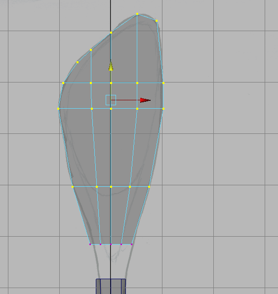 cylinder I know the top faces will be deleted when joining the two shapes. After moving the vertices to make the shape I realised that scaling the sides together makes a more consistent shape. Starting with 8 subdivisions this was not working to enable me to make and join the shapes. I redid the cylinder with 12 realising how many vertices were needed for making the shapes and later join them. Looking back I think it might have been possible with 8.

I started moving the vertices to make the shape of the front and back of the spoon and found it was not working, then using extrude for the faces I experimented and found using scale and move I was able to adjust the shape and faces to get the rounded shapes. After getting the basic shape I then added some extra edge loops around the indented, inside of the spoon to clearly define the ridge on the edge of the scoop shape.
When lining up the vertices I was unable to work out which ones belonged with each other to make the joined shape. The first attempts did not make a symmetrical shape, twisting on one side. Undoing and lining up the shapes again I needed to add two extra edge loops, one centre front and one centre side to help me line up the vertices and shape. Then combining the two meshes and merging the vertices I was able to establish a clear, symmetrical shape. After this I realised I could delete the two extra edges I had made to help me line up the shape evenly and still keep my original shape while adjusting the vertices along the join.
The corners of the original box shape have become a bit lost in the spoon shape. They are still quads and I’m not clear if what I have done was the most appropriate place and way to move the box corners. The other thing is that they have impacted on adding and adjusting edge loops.


The adventures of making a Dalek: in class we did get further with this than the image shows.
2013 – MECHANICAL ARM EXERCISE
Final project sequence, click here and password is marm108


After working in the greys of the Maya interface it is exciting to see the environment start to come alive with textures, lighting, colour and the animation of the mechanical arm introducing some personality.
My Mechanical Arm Test


https://vimeo.com/67488072
password : mArmTest
MAY
 Starting the mechanical arm base and having a bit of a test with the base. Working out how to select faces, edges and vertex selectively and not collecting many others not required to change the shape. Select > convert selection and going inside the shape were very helpful. After starting the model I remembered how helpful it was to make it straight along only the y axis and to keep it central to the grid.
As I worked up the arm parts I was experimenting with working out how to make the shape that could be fit inside each arm block so that it could extend and retract the length of the arm. Thinking that a lattice deformer would be the way to go I soon discovered it was not very helpful and went back to component mode to make the adjustments.
The joining of two parts for the construction of the elbow was challenging. Working out the shapes with the edges and vertex being able to join and merge took several attempts.
The wrist section was a challenge in working out how to make a joint that would work both in the movements to pick up the box and the skill to model the shapes. One of the ways I explored was a ball shape like the base, shoulder joint and there was not enough range of movement and I could not work out how to attach the finger shapes. I changed the pieces of the joint and settled on a flat circular shape that would rotate and more suitable to attach the finger parts so they could move to pick something up.


While working on ideas to attach the fingers part to the wrist joint I explored a few options and came across many problems with my modeling. How do I to make the connecting shape? Which parts do I delete, how will it support the parts, how will it move and do I connect the parts making it workable and not too chunky? I become so caught up in making it work I forgot to think about other alternatives and thanks to Simon he suggested breaking it up into three sections when making three parts of one object was not working. Bless his cotton socks.

Back to the base, I was working on the legs to support the circular structure for the rotation movement of the shoulder section and I explored extrude, lattice and component options and could not get close to the shape. Again Simon had a workable solution and the soft select on the poly extrudes worked like a treat and home I went to make the shape. It took several attempts, I was not able to work out how work on the extrude to make it symmetrical. I adjusted the vertex points and need to work more on that area.
Class Mechanical Arm included exploring curves.
 While making the class mechanical arm one of the concepts we developed was making a pattern. From a series of nurb shapes placed along a line and using surfaces > loft we created the initial shape that became the pattern. Had a big surprise when the shape was deformed due to choosing the nurb shapes in the wrong order.
This decorative shape for the mechanical arm changed the nurbs circle into a square with linear degrees and four sections as part of the inputs in the CB. Finally worked out that after placing the first nurbs shape on the cv curve freezing transformations sets the CB to ease the rotate of the duplicated shape on the curve.
Also managed to get the C, snap to curve happening. After doing a test loft it was interesting to see how the shape could be changed by moving the nurbs circle and adjusting the CV points to improve the shape.
Other areas we explored were deformers for shapes together with duplicate special to rotate 7 rods around the cylinder. The bend deformer has been used to make the twisting shape of the rods around the base shape. Not sure about the relationship between lattice and its base.

APRIL

Discovering Image Planes, they display images for modelling, textures, reference concept drawings and images sequences for live action which may or may not be attached to a camera (cane be any type of camera), can be resized and may or may not be included in the final render. Here we are using a live action background. When including the image as part of the render be aware of the Colour Space options for Colour Management. Consider using RGBA Display Mode when the image will be rendered and used for compositing shots. Adjust Colour Gain for brightness and Colour Offset for contrast. Alpha Gain adjusts the transparency of the image, adjusting the opacity. There will always be some lens distortion from photographs.
Revisiting the ufo model and animation on live action footage. When opening the image plane and the legs are missing, possibly something to do with different versions of Maya.
– the legs were missing though the names were still in the outliner. When remaking and animating the legs, grouping not parenting has a transform node. To animate the The tool setting needed to be on object.
The lights needed to be adjusted to work with the image plane and legs then added a third light.
ufo movie on vimeo, click here : password ‘ufo108’
Discovering Modelling from Autodesk Books
Introducing Autodesk Maya 2013 and Mastering Autodesk Maya 2013
Solar System video – click here – from the book, many hours, like heaps of hours. Please to say a few years later and looking back on this, things have improved, including my wordpress skills.
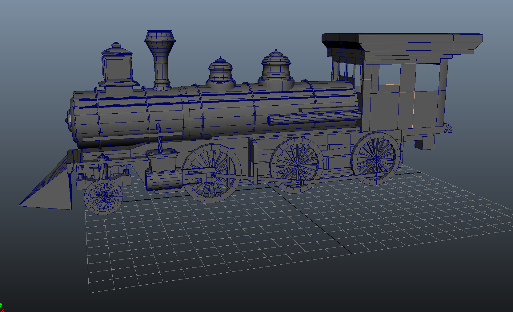
Locomotive
Still going with the locomotive engine – using polygon modeling, CV curl tool, and the outliner grouping and using layers. Learning about to 
 approach the whole and how elements join together to form the engine. Suggested things to model : dining room table and chiars, computer monitor with it s angles and overall surface details, desk or floor lamp, pen, computer mouse, chess set, fruit, car.
Questions – where to find some of the numbers in the CB. AE for extrude, adjust vertex. Evenly scaling and extrude on a poly cylinder.
Modeling Steam Locomotive – exercise from the book, 6 hours. Have done the boiler engine, undercarriage, chimney, lantern, boiler caps and some of the side attachments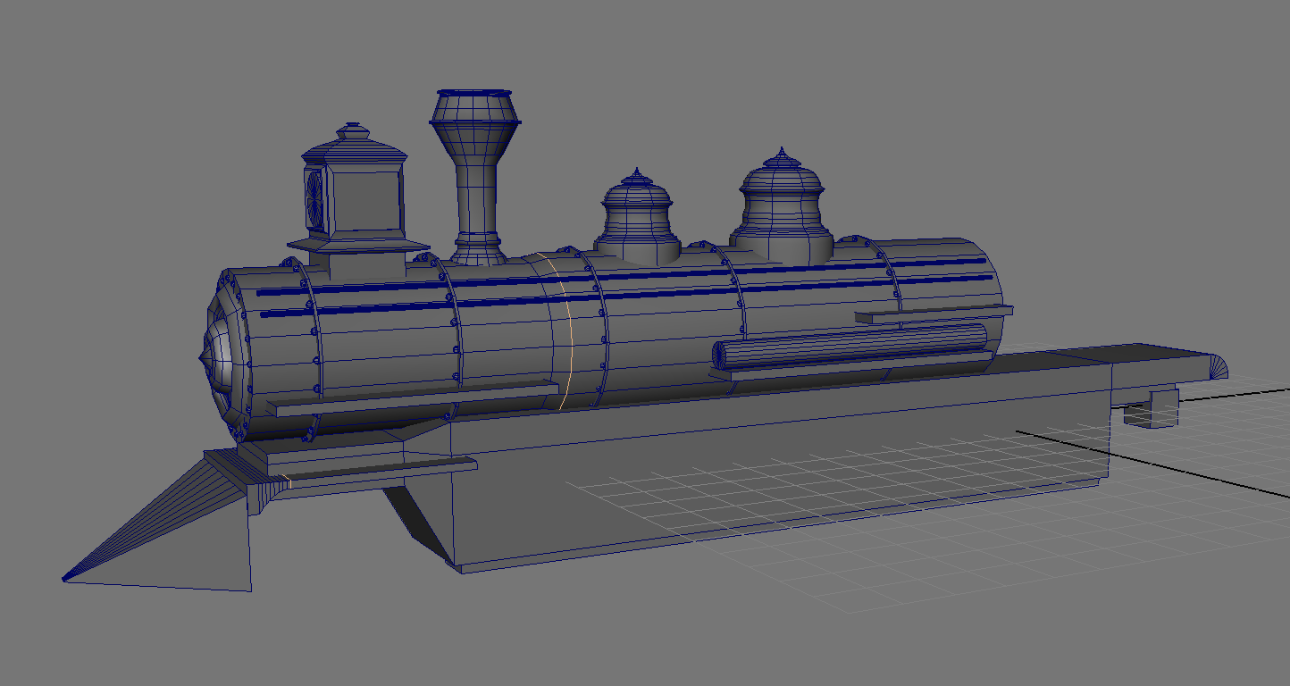
 – using the outliner to organise components and groups of objects
– used poly for cylinder and cube, cv curve, extrude and scale and move to form shapes, shift pivot point to set bolts, rotate and duplicate
– set up layers in the channel box to hide groups when working on other sections
Modeling a Nurbs Pump, from Autodesk Maya book.
 On the duplicate cylinder the pivot point was different for the three objects – the cylinder and the two ends. When I scaled the second cylinder the book had the rescale for x and y changing, leaving z and this distorted the cylinder and shortened the length. I needed it to stay as a cylinder, the same length and reduce the diameter, I changed y and z and left x.
It was interesting to choose the hull in the marking menu to close the ends of the caps instead of attempting to select the cv’s. I needed to redo one cap the lack of isoparms changed how it shaped.
When it came to lofting the two cylinders together I had them too far apart and could not work out how to move one cylinder closer to the other. When I selected the whole group or made it a group it did not move as a group. At this point I had connected the caps to the cylinders by using loft>attach surfaces>detach surfaces. Not sure I was clear on which isoparm needed to be selected to detach surfaces. When attaching surfaces one was going to the wrong place so I did another loft, attached and detached the surfaces.
Chugging along then the last attachments of the top cylinder to the lofted surfaces, the gaps did not match. I had cut too much from one end that needed to be attached. Also not sure how the cv’s needed to match up. There were some gaps in the model and some of the edges had a triangular gap.


Starting out with my modelling learning, my first revolved surface, not so complicate.
MASTERING AUTODESK MAYA 2013 Todd Palamar with Lee Lanier and Anthony Honn

Space Girl concept art by Chris Sanchez http://chrissanchezart.com
The model from Mastering Maya 2013 is based on a design created by Chris Sanchez with the intention of introducing as many modelling techniques as possible. Here are some snap shots from going through the process, following the information, discovering different ways to go about modelling and learning more about how Maya works.
NURBS and CURVES
Started modelling Space Girl’s helmet using Nurbs and Curves
-

- model reference set as image planes, front and side views and visible in perspective.
-

- Detached sections of a NURBS sphere creating a new surface.
-

- Adjusting CVs, lining up the shape with the reference.
-

- Selecting open edges, isoparms of two surfaces creating a loft between them.
-

- Lofted surface’s hulls adjusted making the new shape.
-

- Intersecting surfaces creating a new curve where the two surfaces interest.
-

- the resulting curve from the intersecting surfaces, the other sphere has been hidden
-

- Trimming, hides the other object. Duplicate the curve and creating a lofted surface.
-

- Fillet surfaces to bridge gapes between surfaces.
-

- Railed surface, the profile curve between to curves.
-

- Adjusting the shape of the rebuild, profile curve
-

- Creating the brail surface. First selecting the profile curve, then the first and second rail curves.
-

- Loft created between the inside edges, then adjust the hulls to match the reference.
-

- Adjusted hulls of the lofted surface.
-

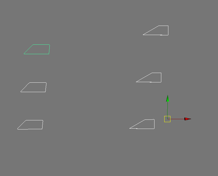
- Creating multiple curves in preparation for lofting across them.
-

- Adjusting Cvs of the lofted surface.
-

- All the parts starting to come together.
-

- The supplied finished helmet.
-

- Started with the technique – box modelling.
-

- Looking at tool settings to begin adjusting vertices for the basic shape.
-

- Soft select to move vertices for the front view’s basic shape.
-

- Adding edge loops then using new vertices to continue shaping the torso.
-

- Extruding faces to make a depression for the arms and helmet.
-

- Divisions with the extrude tool.
-

- Depressions for the arms and helmet.
-

- Selecting faces for deleting.
-

- Deleted faces
-

- Extruding when the object is selected, settings for Thickness and Divisions.
-

- Extruded faces.
-

- Crease Tool.
-

- Crease Tool used on the edges.
-

- Positioned the socket in the opening of the torso.
-

- Creating a Crease Set.
-

- Creating the basic shape from a pipe for the shoulder amor.
-

- Extrude and scale the faces.
-

- Mirror Cut plane and settings.
-

- Mirror cut geometry and nodes that have been created.
-

- Final shape model from the book.
-

- Lattice deformer to shape the geo.
-

- Adjusting selected lattice points to create a bend in the surface.
-

- Soft Modification adding slight spherical bend to the surface.
-

- Creating the boult using two meshes.
-

- Extrude faces with Divisions, to make the indent.
-

- Combining two meshes.
-

- Refining the shape with creasing edges.
-

- The bolt shape.
-

- Positioned bolt and combined with shoulder amor object.
-

- Creating offset curve from original curve.
-

- Joining the curves and shaping using CVs.
-

- Projecting the curve shape on another poly surface, moving CVs adjusts the projection.
-

- Bevel edges to round the shape.
-

- Round cap ON, Inputs settings adjusted.
-

- Extruding faces making the extended geo.
-

- Curve between the two connectors.
-

- Extrude along the curve creating the tube
-

- Curves drawn on ‘Live’ surface, extrude mesh along the curve making the tube.
Had problems with joining the curve to make the S shape and using the Tangent Constraint for the extruded tube on the curves, was not able to find Axis X for the polygon cylinder settings.
MORE NURBS, BOOLEANS and ARTISAN
-

- CV Curve
-

- Revolve from the CV curve.
-

- Converting Nurbs to Polygons.
-

- Belly pleats ready for more modelling, including creasing.
-

- Edge to curve and extrude.
-

- Can then refine the shape.
-

- Object lined up to cut a hole in the mesh.
-

- Hole cut by Booleans, difference operation.
-

- Sphere shaped and merged using a union operation.
-

- Starting with a cube for fabric.
-

- Sculpting the basic shape of the fabric.
-

- Refining the shape of the fabric.
ADVANCED POLYGON-EDITING TOOLS
-

- Append a Polygon

-

- Bowties
-

- Interactive Split Tool


-

- Spin a Polygon edge


-

- Bridge Polygons

-

- Number of subdivisions
Split Polygon Tool is still in the software even though it has been removed from the menu items. Can activate the tool by typing the commands in either the command line or script editor and it can be put on the shelf.
SplitPolygonTool and InteractiveSplitTool
SubDs
The next section for 2013 is SubDs, now gone, yes where are they. According to forums: Attribute Editor > Shape Node > Smooth Mesh >Subdivision Levels or topMenu > Mesh Smooth. No longer a sub primitive option or edit subs menu tab. Hierarchical Subdivisions Surfaces have been removed from the UI in Maya 2014, polygons and smooth approximation have taken over. Smooth Approx is the same as SubD surfaces, the same as the 3 key. It is recommended peoples the Smooth Mesh.
All the MEL commands for subdues still work.
THE AUTHOR’S FINISHED MODEL – Todd Palamar
-

- front
-

- side
-

- back
ANIMATING FACIAL EXPRESSIONS USING BLEND SHAPES
A sense of achievement when there is enough understanding that I can start to think about what to expect before clicking the buttons and if it does not happen process why this has happened. This may be more rigging, have put it here as it is a continuation of the exercises in this book. It does come under Animating Facial Expressions in the book so not sure.


-

- Set Driven Keys to connect the controller to the blend shapes., mouth wide.
-

- Set Driven Keys to connect the controller to the blend shapes., mouth narrow.
-

- Set Driven Keys to connect the controller to the blend shapes for left and side mouth.
-

- Showing each side of the mouth has a different shape.
SUBDIVISION SURFACE MODELLING
Subdivision Surface modelling is the same as Polygon modelling with the biggest difference being the use of levels. Levels can easily be converted to surfaces. All surfaces are attached and there are no issues with having the curves break up.
MAYA MODELLING PREFERENCES
NURBS MODELLING Maya Version 6
NURBS
When using a curve to make a surface with either Loft or Birail Tool, maintain a netted structure with uniform distributed isoparm arrangement. NURBS use UV coordinates, the surfaces are not attached and realistic multi-patches becomes tricky and time consuming. Maya’s renderers when rendering NURBS surfaces use tessellations generating the finished produce using polygon faces. Radiating NURBS modelling preserves smooth curves.
NURBS modeling – Introduction to 3D Modeling
REBUILD CURVE OPTIONS
REBUILD TYPE
- Uniform – rebuilds the curve using a uniform Parameter value, will not be able to adjust the values for Number of Spans and Degree
- Reduce – rebuilds curves by deleting unnecessary knots based on the Tolerance Setting, higher the value the more knots are deleted, Global value in the Preference Settings, Local is the user’s settings
- Match Knots – rebuilds surfaces with the Degree, Knot and Span values in accordance with another curve
- No Multiple Knots – deletes supporting curves created during the Rebuild process. A new surface will be rebuilt using the same values of the rebuilt uniform surface.
- Curvature – creates a knot at the highest curvature assuming the degree value of the original curve
- End Condition – rebuilds by specifying the location of the End CV and Knot
PARAMETER RANGE
Used for rebuilding surfaces with the Parameter Range value of teh adjacent surface in attaching two surfaces and aligning the curvatures.
- 0 to 1 – sets the MIn Max Range to 0 to 1
- Keep – maintains that of the original curve, surface
- 0 to # Span – creates a positive number of knots, mostly used with Rebuild Type Uniform. Matches the Parameter value with the Span value, if the surface has 5 spans then the Parameter Range is also set from 0 to 5
- Direction – rebuilds in the U-and/or V-direction
- Number of Spans U, V – establishes the span value of the surface to rebuild in either direction
KEEP
- To set the end point of the original curve set Ends, Tangents, CV or NumSpans to ON
NUMBER OF SPANS
- Will rebuild the curve according to this number
DEGREE
- Specifies the degree of teh curve, 1 Linear will rebuild a straight line
KEEP ORIGINAL
- Preserves the original curve when rebuilding a new curve
USE TOLERANCE
- Set to Global the values specified in Preferences are used, when set to Local the values entered by the user are used
SURFACES
BIRAIL 1, 2 and 3+ TOOL
- Transform Control – Non Proportional maintains the height of the surface as it narrows, Proportional gets proportionally smaller as it narrows. Can be changed in INPUTS
- Continuity – the tangent of the surface succeeds the surface with the profile curve with Birail 2 and 3+ contains both the profile option and rail options of each curve
- Rebuild – rebuilds the checked curve
- Output Geometry – NURBS or Polygons
- Tool Behaviour – Exit on Completion is Off can continue using the tool, Auto Completion ON will display a prompt at each step
Birail 2 Tool difference is that it uses 2 profile curves with the starting and ending points of the profile curve and rail curve coinciding.
Birail 3+ Tool has 3 or more profile curves
LOFT TOOL
Creates surfaces that links curves together including an isoparm and a new curve.
- Parameterization – Uniform knot spacing makes the profile curves run parallel to the V direction. The parameter values of the resulting surface in the U direction are equally spaced. The first profile curve corresponds to the isoparm on the surface at U[0], the second to U[1], and so on. Textural spacing based on the span. Chord Length spacing causes the parameter values on the resulting surface in the U direction to be based on the distance between the start points of the profile curves. Texture is evenly applied without regards to the span.
- Auto Reverse – Automatically aligns differing curve directions, when off the curves will be lofted in their various directions to produce a twisted surface.
- Close – On will close the surface in the V-direction.
- Section Spans – divides the span between each curve according to the designated value
- Curve Range – Complete links together the starting and end points, Partial allows for the specification of the scope of the curve and names the lofted curves.
- Output Geometry – NURBS, Polygons, Bezier
In general, Uniform surfaces and Chord Length each have different parameters. These parameters determine how the curvature will be distributed, how the surface will be defined in the texture mapping and how the surfaces will be attached when using Attach Surface or Stitch.
- Uniform Surface takes on the same values as the edit point. When drawing a curve the parameters of a uniform surface coincides with the span of the surface or curve
- Cord Length surfaces, the parameter is determined by the curve or surface length.
ATTACH SURFACES
OPEN/CLOSE SURFACES
MOVE SEAM
BOUNDARY
STITCH TOOL
STITCH EDGE
Used to stitch two surfaces
GLOBAL STITCH
Can be applied to several surfaces at a time
NURBS MULTIPATCH MODELLING
- create the NURBS for each part of the model
- adjust the points using such as a Lattice Deformer (delete history), Inserting Isoparms, moving CVs
- may need to Reverse Surface Direction for Lofted surfaces from curves depending on how the surface was lofted
- detach surfaces, paying close attention to how the surfaces were detached
- rebuild the surfaces so that each surface can have the same Span value
- stitch together the areas where the surfaces meet
- delete history
- adjust CVs
- add detail after attaching the surfaces then detach the surfaces, returning them to their original state, may need to rebuild again
- global stitch after selecting all the surfaces
- filling any spaces use Boundary to make the boundary surfaces
- make a mirror copy
- convert to polygons
How are surfaces divided for animation? What is the effect of incorrect surface divisions? Surface divisions needs to provide for movement, preventing animation surface splitting while maintaining the shape so there are not abnormal alternations occurring in the skin. Refrain from dividing surfaces in joints, where there is a lot of movement and instead, divide surfaces in areas with little or no movement such as where the arm meets the body.
CURVES
MAKE THE SELECTION LIVE can create objects such as curves directly on a surface
POLYGON MODELLING
Produces shapes with an infinite number of angles, can attach surfaces, all 3D software supports the Polygon method of modelling.
ALLIGN TOOL manipulator is used to quickly and easily align a selected object to another object.
SNAP TOGETHER TOOL point on one object, the point on another object that it will be connected to snapping the point of the first object to the point on the second object.
ANNOTATING attaching a label to an object in the scene
POKE FACES adding a vertex to the selected surface to newly divide up the surface
WEDGE FACE extrude faces including as an arc along an edge
BOX MODELLING
Digital Media World February 2001, Issue #21
MODELLING PROCESS DIARY
3D Modelling is based on the Cartesian coordinating system in three dimensions, a point in 3D space defined by width, height and depth.
The zero point for each of these axes is the origin and the intersection of all three axes, providing the starting point for calculations and defining a point in 3D space or World Coordinates Position, (0,0,0). This defines the World Space, origin and the position properties indicate how far away the object is from the origin. World space coordinates tell exactly where an object is in relation to the rest of the scene.
Each object is also defined by its own object space or local space. If the geometric centre of an object is not centred at the origin and is centred at its own local space even when placed at origin it will be off-centered from world space. Object space coordinates are relative to the object’s initial position.
Maya uses the right-handed Cartesian coordinate system, where the X axis points left to right, the Y axis is up and down and Z points forward and backwards.
Modelling uses many techniques including polygonal modelling, NURBS and subdivision surfaces or SubD. They have pivot point which is where objects rotate and scale from and is the placement point for the X, Y and Z coordinates. It can be the object or another node’s pivot point within a network of nodes and hierarchies.
Maya uses nodes to carry attributes such as coordinates, geometric descriptions, colour values. The transform node or DAG node (direct acyclic graph) has the values for translation (position), rotation and scale and also hold hierarchy information about any other child or parent nodes that are attached. Another node defines the shape, creation node or shape nodes, how the object was created with attributes such as radius and the shape nodes are the children of the transform node.
Normals, http://www.3dtutorialzone.com/ define the way the model is shaded, how its built, which faces are facing outwards, what’s the front and back of the surface, etc. Without normals, all your models would be silhouettes.
Topology: whatever type of geometry you use it will either be created by NURBS, or points, edges, and faces. The way these components are connected together and the flow around the 3D object is the topology. You can think of topology as the type of polygon faces, the type of vertices and the flow of the edges.
Uniform Tessellations using the same intermediary values, including Polygon Count.
Adaptive Tessellations creates more polygons in detailed regions to express the precision of the surface.
Divisions Per Face decides how many times each surface will be sliced.
Polygon Count where the value is changed for the number of polygons and can include a Maximum Number.
Retopologising to create an animatable mesh. To create a mesh which is suitable for deformation, so all the edge loops will be carefully considered in pursuit of this.
When scaling objects consider the difference between using the scale tool or changing the radius to adjust the size.
Rotation, Heading, Pitch and Bank.
Cinema 4D: converting primitive state, paramedic object, into polygonal object, moving from mathematically defined geometry to object that user can define, such as repositioning the axis. Make Editable. Enable Axis Modification. Scale Document function can quickly adjust the scale without messing up the scale settings in the coordinates tab. The Scale Project function works on everything in the document, can isolate objects by copying and pasting them int a new empty file, make the changes and copy and past them back. Edit > Current Scale > Target Scale.
Important considerations are the flow of topology, designing the topology so it will deform properly when animated. Typically, horizontal and vertical lines of topology will run through the entire character to define the overall shape and loops of edges to define areas of deformation e.g. muscle mass. Aim to define the shape with the least amount of detail as possible.
Key 3D Modeling Terminology Beginners Need to Understand
NODES hold specific information and any actions associated with that information such as a surface, light or camera material.
POLYGON MODELLING
Polygon Modelling and Polygon Terminology
The components of polygon surfaces are made up of faces that share three or more edges and vertices or points along the edges which are used to create hard-surface models. A mesh is is a collection of vertices, edges and faces that defines the shape. It is a closed plane figure, enclosed by lines that form many angles with the lines creating edges. A polygon mesh is the surface that is composed of points or vertices that form an edge that shares at least two adjacent polygons.
A polygon mesh’s orientation is defined by its normal vector, normal which tells the computer whether the polygon is facing outward or inward.
When three polygons share the same edge a non-manifold surface is created which can lead to rendering and animation problems, having a configuration that cannot be unfolded into a continuous flat piece. There is also a problem where two polygons share a single vertex but not a complete edge.
Polygon Faces have two surfaces with normals determining a surface’s orientation affecting such things as visibility, rendering, dynamics, lighting and shading.
Splines are lines or curves with control points (control vertices) for modification which can either approximate a curve or interpolate it being influenced by adding more control points or vertices, spline curve weighting. Linear, Cardinal, Bezier, Hermite, B-spline (basic spline), Nurbs (Nonuniform rational B-spline) and spline patch.
Surface Modelling
Solid Modelling
Split Polygon Tool is still in the software even though it has been removed from the menu items. Can activate the tool by typing the commands in either the command line or script editor and it can be put on the shelf.
SplitPolygonTool and InteractiveSplitTool
NURBS MODELLING – Non-Uniform Rational B-Splines and CURVES
You can use NURBS in two ways:
- Construct 3D models from NURBS primitives.
Primitives are simple 3D objects created in the shape of common geometric forms such as cubes, spheres, cones, and so on. Primitives can be a great starting point for many 3D shapes. You can modify the attributes of NURBS primitives to modify their shape. You can also modify NURBS primitives by trimming away portions of their forms, beveling their edges, or by sculpting them into different shapes using sculpting tools.
- Construct NURBS curves that define the basic outline of the 3D form you want to construct, then use the curves as a basis for constructing NURBS surfaces.
To find options for constructing and modifying NURBS curves and surfaces:
- You can draw curves by placing control vertices, or edit points. The curve drawing tools are found in the Create menu.
- The options for creating and editing NURBS curves and NURBS surfaces are found in the Modeling menu set.
- You can also find NURBS options on the Curves/Surfaces shelf.
Nurbs modelling is suitable for models that benefit from smooth surfaces and contours, they are four-sided patches and are automatically converted to triangles at render time. Tessellation, how the surface is covered to triangles, settings can be changed at any time thus being able to change the resolution.
Nurbs are made up of curves, curve points, which are lines defined by points with movement defined by its U-coordinates, the location of a point along the length and the position of the point is defined by its U-parameter. The V-coordinate specifies the location of a point on the surface, U and V are perpendicular to each other.
Linear and cubic surfaces with the curves referred to as isoparms, isoparametric curve.
Curves can be made up of multiple spans with edit points marking the connections between two spans. NURBS curves and surfaces are controlled with the points or control vertex (CV), the CV’s are handles used to edit the curve’s shapes. Hulls are straight lines that connect the CVs, a visual guide and groups of CVs that follow the curves that define a surface. Parameterisation is the way the points along the curve are numbered, Uniform or Chord Length.
Nurbs surfaces can be edited by moving the position of the CVs or hulls of a surface. There are seams where the end of the surface meets the beginning.
CV curve default is will a degree of 3 creating smooth, rounded curves and needs a minimum of four CVs for the curve.
Starting with NURB modelling they can then be converted to polygons for further modelling. The tessellation methods for converting NURBS to polygons can be Control Points, General which is based on the number of U and V values or the number of contiguous edges that will wrap around your model, Count where I can enter a target value for the number of polygons and Standard Fit which has a criterion for subdividing the model.
MAYA SURFACE MODELING NURBS Birail TOOL AND ITS OPTIONS
BOOLEAN OPERATIONS
A Boolean operation creates a new surface from two surfaces to create a new surface and works best when the geometry is kept simple. Union which adds two surfaces, Difference subtracts two surfaces Intersection which overlaps parts of two surfaces.
Booleans can leave n-sided polygons and overlapping edges which gives us bad topology.
SUBDIVISION SURFACES for MODELLING
Autodesk Maya Subdivision Surface Modeling
Convert Polygons to Subdiv
With subD’s the mesh can be subdivided to add detail only where it is needed. Always create UV texture before converting polygons to subDs. Keep the polygon mesh as simple aspkossible, can convert three-sided or n-sided polygons though will get better results with four-sided polygons and non manifold geometry is not supported. Subdivision surfaces are largely unsupported in pipelines outside of Maya.
The next section for 2013 is SubDs, now gone, yes where are they. According to forums: Attribute Editor > Shape Node > Smooth Mesh >Subdivision Levels or topMenu > Mesh Smooth. No longer a sub primitive option or edit subs menu tab. Hierarchical Subdivisions Surfaces have been removed from the UI in Maya 2014, polygons and smooth approximation have taken over. Smooth Approx is the same as SubD surfaces, the same as the 3 key. It is recommended peoples the Smooth Mesh.
All the MEL commands for subdues still work.
USING DEFORMERS
You can use deformers as modeling tools for shaping NURBS or polygonal objects. When you are finished modeling, be sure to delete the deformer along with the rest of the object’s history. Note that in the context of modeling, an object’s history can be called its construction history.
Maya: Deformers by Minkyung Choi. With Maya’s deformers, you can quickly build and animate deformed surfaces with a high level of control.
MAYA DEFORMER BASICS FOR CREATING AND ANIMATING STUFF A basic look at using deformers from our old friend Stuart Christensen where he shows how deformers can be used for modeling and for animation as well.
MODELS for the INTEGRATED PROJECT
Design Visual Thinking
Link to how my Design Visual Thinking Integrate Project evolved.
ROSE the APRON
I started by thinking about the box size, do I include the head or start with the basic body. Where will I need the edges, the vertices, the faces and how many subdivisions will be required to create the shape? I was planning this for the arms, legs and character detail at the beginning and not approaching it from a basic cube and building from there. Starting with all of that and forgetting to “keep it simple for as long as possible”.
By doing this I found it difficult to control the components of the model. Adding more and more was not the solution, the edges were not connecting, I was not working out how to create the quad faces and how to create the character’s shape.
After making the basic box shape, creating the band around the body then extending the arms I had an odd arm shape. This was not how extruded faces were meant to look, I could not work out why the smoothed model was this odd shape. It turned out to be a nonmanifold surface, too many faces hanging out together. I later had the same problem with the hair, working it out and improving my extrude technique then there was hair.
I could not work out where to extrude the leg from. Deleting the faces and bridging with divisions, like we did for the penguin was not working. The number of edges I needed to extrude for the legs was not lining up with the edges on the body. I went back to 4 faces and redirected edges to create a face to extrude for the leg. Still I was extruding the leg each time there was a change in the shape of the leg. Eventually I extruded once making the shape, later adding edge loops and moving and scaling to make the shape.
I made a separate box model for the foot with the same number of edges as the leg. Then combining the mesh and merging the vertices with merge vertex tool.
The first time round was more about getting it wrong and learning some basic modeling techniques and tools.
Now I understand more about having edge loops that connect and go around the shape, making it easier to add edge loops later and placing them to give more definition and sharper edges. This gave more control over the vertices including when and how they are moved to create the shape. A model can be built by both extruding faces and deleting faces then extruding the edges giving more choices and levels of control while keeping the geometry simple.
The band around the character works well with the arms extending from there. I like the face as the top part of the apron. Next time I would prefer a flatter character making it more apron like with hair ties that are not so wide and more like ties.
Basket
Starting with a box shape and four subdivisions for width and depth and two for height. When making the shape first and sloping the top it was difficult to extrude to make the rounded shape along the top rim. Going back I kept the basic box shape and extruded creating the faces and shapes for the round lip shape at the top of the basket opening. Then I shaped and moved the vertices to create the rounded shape for the top of the basket being aware that the inside shape needed to stay inside and not protrude through the outside faces.
Smoothing the model’s surface, the edges, can be done with smooth preview or converting the polygons in the Mesh menu.
Smooth Mesh Preview affects only the display of the polygon mesh in the scene view, when rendered it will appear in its original un-smoothed state in the final image, using Mental Ray the geometry appears smoothed in the render. Converting the smooth preview to a smoothed polygon mesh using Modify > Convert > Smooth Mesh Preview to Polygons or to a subdiv proxy using The Smooth operation subdivides the geometry, quadrupling the number of polygon faces in the geometry and increasing the number of vertices available for modelling unlike the smooth preview where the vertices stay the same.
Wooden Spoon
Using two shapes, a box for the top and a cylinder for the handle I’m not sure what to do about the triangles at end of the cylinder shape. With the cylinder I know the top faces will be deleted when joining the two shapes. After moving the vertices to make the shape I realised that scaling the sides together makes a more consistent shape. Starting with 8 subdivisions this was not working to enable me to make and join the shapes. I redid the cylinder with 12 realising how many vertices were needed for making the shapes and later join them. Looking back I think it might have been possible with 8.
I started moving the vertices to make the shape of the front and back of the spoon and found it was not working, then using extrude for the faces I experimented and found using scale and move I was able to adjust the shape and faces to get the rounded shapes. After getting the basic shape I then added some extra edge loops around the indented, inside of the spoon to clearly define the ridge on the edge of the scoop shape.
When lining up the vertices I was unable to work out which ones belonged with each other to make the joined shape. The first attempts did not make a symmetrical shape, twisting on one side. Undoing and lining up the shapes again I needed to add two extra edge loops, one centre front and one centre side to help me line up the vertices and shape. Then combining the two meshes and merging the vertices I was able to establish a clear, symmetrical shape. After this I realised I could delete the two extra edges I had made to help me line up the shape evenly and still keep my original shape while adjusting the vertices along the join.
The corners of the original box shape have become a bit lost in the spoon shape. They are still quads and I’m not clear if what I have done was the most appropriate place and way to move the box corners. The other thing is that they have impacted on adding and adjusting edge loops.
The adventures of making a Dalek: in class we did get further with this than the image shows.
2013 – MECHANICAL ARM EXERCISE
Final project sequence, click here and password is marm108
After working in the greys of the Maya interface it is exciting to see the environment start to come alive with textures, lighting, colour and the animation of the mechanical arm introducing some personality.
My Mechanical Arm Test
https://vimeo.com/67488072
password : mArmTest
MAY
Starting the mechanical arm base and having a bit of a test with the base. Working out how to select faces, edges and vertex selectively and not collecting many others not required to change the shape. Select > convert selection and going inside the shape were very helpful. After starting the model I remembered how helpful it was to make it straight along only the y axis and to keep it central to the grid.
As I worked up the arm parts I was experimenting with working out how to make the shape that could be fit inside each arm block so that it could extend and retract the length of the arm. Thinking that a lattice deformer would be the way to go I soon discovered it was not very helpful and went back to component mode to make the adjustments.
The joining of two parts for the construction of the elbow was challenging. Working out the shapes with the edges and vertex being able to join and merge took several attempts.
The wrist section was a challenge in working out how to make a joint that would work both in the movements to pick up the box and the skill to model the shapes. One of the ways I explored was a ball shape like the base, shoulder joint and there was not enough range of movement and I could not work out how to attach the finger shapes. I changed the pieces of the joint and settled on a flat circular shape that would rotate and more suitable to attach the finger parts so they could move to pick something up.
While working on ideas to attach the fingers part to the wrist joint I explored a few options and came across many problems with my modeling. How do I to make the connecting shape? Which parts do I delete, how will it support the parts, how will it move and do I connect the parts making it workable and not too chunky? I become so caught up in making it work I forgot to think about other alternatives and thanks to Simon he suggested breaking it up into three sections when making three parts of one object was not working. Bless his cotton socks.
Back to the base, I was working on the legs to support the circular structure for the rotation movement of the shoulder section and I explored extrude, lattice and component options and could not get close to the shape. Again Simon had a workable solution and the soft select on the poly extrudes worked like a treat and home I went to make the shape. It took several attempts, I was not able to work out how work on the extrude to make it symmetrical. I adjusted the vertex points and need to work more on that area.
Class Mechanical Arm included exploring curves.
While making the class mechanical arm one of the concepts we developed was making a pattern. From a series of nurb shapes placed along a line and using surfaces > loft we created the initial shape that became the pattern. Had a big surprise when the shape was deformed due to choosing the nurb shapes in the wrong order.
This decorative shape for the mechanical arm changed the nurbs circle into a square with linear degrees and four sections as part of the inputs in the CB. Finally worked out that after placing the first nurbs shape on the cv curve freezing transformations sets the CB to ease the rotate of the duplicated shape on the curve.
Also managed to get the C, snap to curve happening. After doing a test loft it was interesting to see how the shape could be changed by moving the nurbs circle and adjusting the CV points to improve the shape.
Other areas we explored were deformers for shapes together with duplicate special to rotate 7 rods around the cylinder. The bend deformer has been used to make the twisting shape of the rods around the base shape. Not sure about the relationship between lattice and its base.
APRIL
Discovering Image Planes, they display images for modelling, textures, reference concept drawings and images sequences for live action which may or may not be attached to a camera (cane be any type of camera), can be resized and may or may not be included in the final render. Here we are using a live action background. When including the image as part of the render be aware of the Colour Space options for Colour Management. Consider using RGBA Display Mode when the image will be rendered and used for compositing shots. Adjust Colour Gain for brightness and Colour Offset for contrast. Alpha Gain adjusts the transparency of the image, adjusting the opacity. There will always be some lens distortion from photographs.
Revisiting the ufo model and animation on live action footage. When opening the image plane and the legs are missing, possibly something to do with different versions of Maya.
– the legs were missing though the names were still in the outliner. When remaking and animating the legs, grouping not parenting has a transform node. To animate the The tool setting needed to be on object.
The lights needed to be adjusted to work with the image plane and legs then added a third light.
ufo movie on vimeo, click here : password ‘ufo108’
Discovering Modelling from Autodesk Books
Introducing Autodesk Maya 2013 and Mastering Autodesk Maya 2013
Solar System video – click here – from the book, many hours, like heaps of hours. Please to say a few years later and looking back on this, things have improved, including my wordpress skills.
Locomotive
Still going with the locomotive engine – using polygon modeling, CV curl tool, and the outliner grouping and using layers. Learning about to approach the whole and how elements join together to form the engine. Suggested things to model : dining room table and chiars, computer monitor with it s angles and overall surface details, desk or floor lamp, pen, computer mouse, chess set, fruit, car.
Questions – where to find some of the numbers in the CB. AE for extrude, adjust vertex. Evenly scaling and extrude on a poly cylinder.
Modeling Steam Locomotive – exercise from the book, 6 hours. Have done the boiler engine, undercarriage, chimney, lantern, boiler caps and some of the side attachments
– using the outliner to organise components and groups of objects
– used poly for cylinder and cube, cv curve, extrude and scale and move to form shapes, shift pivot point to set bolts, rotate and duplicate
– set up layers in the channel box to hide groups when working on other sections
Modeling a Nurbs Pump, from Autodesk Maya book.
On the duplicate cylinder the pivot point was different for the three objects – the cylinder and the two ends. When I scaled the second cylinder the book had the rescale for x and y changing, leaving z and this distorted the cylinder and shortened the length. I needed it to stay as a cylinder, the same length and reduce the diameter, I changed y and z and left x.
It was interesting to choose the hull in the marking menu to close the ends of the caps instead of attempting to select the cv’s. I needed to redo one cap the lack of isoparms changed how it shaped.
When it came to lofting the two cylinders together I had them too far apart and could not work out how to move one cylinder closer to the other. When I selected the whole group or made it a group it did not move as a group. At this point I had connected the caps to the cylinders by using loft>attach surfaces>detach surfaces. Not sure I was clear on which isoparm needed to be selected to detach surfaces. When attaching surfaces one was going to the wrong place so I did another loft, attached and detached the surfaces.
Chugging along then the last attachments of the top cylinder to the lofted surfaces, the gaps did not match. I had cut too much from one end that needed to be attached. Also not sure how the cv’s needed to match up. There were some gaps in the model and some of the edges had a triangular gap.
Starting out with my modelling learning, my first revolved surface, not so complicate.
MASTERING AUTODESK MAYA 2013 Todd Palamar with Lee Lanier and Anthony Honn
Space Girl concept art by Chris Sanchez http://chrissanchezart.com
The model from Mastering Maya 2013 is based on a design created by Chris Sanchez with the intention of introducing as many modelling techniques as possible. Here are some snap shots from going through the process, following the information, discovering different ways to go about modelling and learning more about how Maya works.
NURBS and CURVES
Started modelling Space Girl’s helmet using Nurbs and Curves
-
- model reference set as image planes, front and side views and visible in perspective.
-
- Detached sections of a NURBS sphere creating a new surface.
-
- Adjusting CVs, lining up the shape with the reference.
-
- Selecting open edges, isoparms of two surfaces creating a loft between them.
-
- Lofted surface’s hulls adjusted making the new shape.
-
- Intersecting surfaces creating a new curve where the two surfaces interest.
-
- the resulting curve from the intersecting surfaces, the other sphere has been hidden
-
- Trimming, hides the other object. Duplicate the curve and creating a lofted surface.
-
- Fillet surfaces to bridge gapes between surfaces.
-
- Railed surface, the profile curve between to curves.
-
- Adjusting the shape of the rebuild, profile curve
-
- Creating the brail surface. First selecting the profile curve, then the first and second rail curves.
-
- Loft created between the inside edges, then adjust the hulls to match the reference.
-
- Adjusted hulls of the lofted surface.
-
- Creating multiple curves in preparation for lofting across them.
-
- Adjusting Cvs of the lofted surface.
-
- All the parts starting to come together.
-
- The supplied finished helmet.
-
- Started with the technique – box modelling.
-
- Looking at tool settings to begin adjusting vertices for the basic shape.
-
- Soft select to move vertices for the front view’s basic shape.
-
- Adding edge loops then using new vertices to continue shaping the torso.
-
- Extruding faces to make a depression for the arms and helmet.
-
- Divisions with the extrude tool.
-
- Depressions for the arms and helmet.
-
- Selecting faces for deleting.
-
- Deleted faces
-
- Extruding when the object is selected, settings for Thickness and Divisions.
-
- Extruded faces.
-
- Crease Tool.
-
- Crease Tool used on the edges.
-
- Positioned the socket in the opening of the torso.
-
- Creating a Crease Set.
-
- Creating the basic shape from a pipe for the shoulder amor.
-
- Extrude and scale the faces.
-
- Mirror Cut plane and settings.
-
- Mirror cut geometry and nodes that have been created.
-
- Final shape model from the book.
-
- Lattice deformer to shape the geo.
-
- Adjusting selected lattice points to create a bend in the surface.
-
- Soft Modification adding slight spherical bend to the surface.
-
- Creating the boult using two meshes.
-
- Extrude faces with Divisions, to make the indent.
-
- Combining two meshes.
-
- Refining the shape with creasing edges.
-
- The bolt shape.
-
- Positioned bolt and combined with shoulder amor object.
-
- Creating offset curve from original curve.
-
- Joining the curves and shaping using CVs.
-
- Projecting the curve shape on another poly surface, moving CVs adjusts the projection.
-
- Bevel edges to round the shape.
-
- Round cap ON, Inputs settings adjusted.
-
- Extruding faces making the extended geo.
-
- Curve between the two connectors.
-
- Extrude along the curve creating the tube
-
- Curves drawn on ‘Live’ surface, extrude mesh along the curve making the tube.
Had problems with joining the curve to make the S shape and using the Tangent Constraint for the extruded tube on the curves, was not able to find Axis X for the polygon cylinder settings.
MORE NURBS, BOOLEANS and ARTISAN
-
- CV Curve
-
- Revolve from the CV curve.
-
- Converting Nurbs to Polygons.
-
- Belly pleats ready for more modelling, including creasing.
-
- Edge to curve and extrude.
-
- Can then refine the shape.
-
- Object lined up to cut a hole in the mesh.
-
- Hole cut by Booleans, difference operation.
-
- Sphere shaped and merged using a union operation.
-
- Starting with a cube for fabric.
-
- Sculpting the basic shape of the fabric.
-
- Refining the shape of the fabric.
ADVANCED POLYGON-EDITING TOOLS
-
- Append a Polygon
-
- Bowties
-
- Interactive Split Tool
-
- Spin a Polygon edge
-
- Bridge Polygons
-
- Number of subdivisions
Split Polygon Tool is still in the software even though it has been removed from the menu items. Can activate the tool by typing the commands in either the command line or script editor and it can be put on the shelf.
SplitPolygonTool and InteractiveSplitTool
SubDs
The next section for 2013 is SubDs, now gone, yes where are they. According to forums: Attribute Editor > Shape Node > Smooth Mesh >Subdivision Levels or topMenu > Mesh Smooth. No longer a sub primitive option or edit subs menu tab. Hierarchical Subdivisions Surfaces have been removed from the UI in Maya 2014, polygons and smooth approximation have taken over. Smooth Approx is the same as SubD surfaces, the same as the 3 key. It is recommended peoples the Smooth Mesh.
All the MEL commands for subdues still work.
THE AUTHOR’S FINISHED MODEL – Todd Palamar
-
- front
-
- side
-
- back
ANIMATING FACIAL EXPRESSIONS USING BLEND SHAPES
A sense of achievement when there is enough understanding that I can start to think about what to expect before clicking the buttons and if it does not happen process why this has happened. This may be more rigging, have put it here as it is a continuation of the exercises in this book. It does come under Animating Facial Expressions in the book so not sure.
-
- Set Driven Keys to connect the controller to the blend shapes., mouth wide.
-
- Set Driven Keys to connect the controller to the blend shapes., mouth narrow.
-
- Set Driven Keys to connect the controller to the blend shapes for left and side mouth.
-
- Showing each side of the mouth has a different shape.
