Compositing is the process of putting back together elements of a shot or scene that have been rendered separately. These layers give the compositor the ability to alter elements when finishing before integrating and bringing them together in the final image. In the Post-Production Visual Effects Industry, compositing is a vital step to achieving final, finished shot imagery. Utilizing live-action (shot with actual cameras), digital (created on a computer), and various other elements, the compositor is able to assemble together a final, photo-real image sequence.
COMPOSITING is the process of merging multiple rendered layers of image information into one image to create a final look. The seamless integration of multiple elements that may come from vastly different sources. A successful composite may rely on many techniques, such as keying/matting, colour correcting, rotoscoping, warping and painting. How does the effect look
Expands options, pulling together and integrating elements including from different applications which will affecting the look of the scene and movie.
Optimising production time using layers or passes where drastic manipulation is possible with much less render time giving speed, flexibility, quality and combining different rendering options such as:
- glow
- lens flare
- incandescence
- motion bur
- reflections
- occlusion
- shadows
- object visibility
- alpha channels
- z-dpeth
- depth of field
- masking
- backgrounds
- masking
- backgrounds
- black hole
- matte opacity
- timing
- lighting
- colour matching
- colour correcting
- contrast balance
- edge anti-aliasing
- film grain
- camera shake
- external plates
- video
- texture elements
- flexibility to re-render or colour correct individual elements
- increase creative potential
- flexibility to include some effects
- combine different looks from different renderers
- combine 3D and 2D renders
- only need to render one frame of still images
- render large complex scenes more efficiently
PREMULTIPLY
The mask channel is used to blend the rendered element into the background. Most computer-generated elements are premultiplied. It is an image that has its RGB channels multiplied by its alpha channel. Typically, images rendered by 3D software are premultiplied, meaning that transparent areas have black both in the RGB areas and in the same areas of the alpha channel. In a premultiplied image, the value of the RGB channels is never higher than that of the alpha channel. Do not colour-correct a premultiplied image.
Other NUKE post can be found under THE FOUNDRY on the TUTORIALS, MAGAZINES, LINKS and RESOURCES post.
VFX Breakdown by Jellyfish Pictures: How to Train your Dragon: Homecoming
SOME TECHNICAL THINGS
3:2 PULL-DOWN is a technique to convert film footage to video footage and back again
ALPHA value is an opacity value. Alpha channels are basically a cookie cutter, white areas represent the foreground and black areas represent the background controlling the opacity of an image. TIFF and TARGA FILES can carry an alpha channel. Also called the matte or mask channel. In colour images, the fourth channel after the red, green and blue and in black-and-white images, the second channel after the luminance channel.
ANTI-ALIAS
ASPECT RATIO determines the format
BIT RATE
BLUE SCREEN is an evenly lit, bright, pure blue background used behind images then the compositing process replaces all the blue with another image. A green screen can also be used.
CHROMA KEY electronically matting or inserting an image from one camera into a picture from another. The subject to be inserted is shot against a solid colour background and signals from the two sources are then merged.
CHROMA SUBSAMPLING
COLOUR CORRECTION is a generic term for any process that alters the perceived colour of an image. Often describing RGB in a range between 0 and 1 and generally either mathematically corrected or rearranging of specific colour channels.
COLOUR MATCHING makes the colour of one shot correspond with that of another
CONCATENATION is the process of mathematically combining multiple colour corrections into one
CURVE EDITOR gives a visual representation of animated keyframes on a graph which can be modified
EXPRESSIONS change a parameter’s value over time
FIELDS two separate subframes called fields make each frame of video
FRAME RATE
INTERLACING 2 fields making a frame, film uses solid frames and video uses interlaced fields. The manner in which a television pictures is composed, scanning alternate lines of two video fields to create one frame everyone-thirtieth of a second in NTSC.
IMAGE FORMAT
KEY FRAMES are values set at various frames of an animation changing a parameter’s value over time
KEYING involves extacting an object from an image and combining it with a different backbround
KODAK CINEON 10-BIT LOGARITHMIC file format uses and efficient colour compression scheme based on the idea that the human eye is more sensitive to shadows and midtones than to highlights
LINEAR COLOUR SPACE
LOGARITHMIC COLOUR SPACE
LUMINANCE value is the brightness
MAP SIZE, X and Y determines the RESOLUTION, more precise value use values greater than 512
MASK is an image or part of an image usually used to limit or constrain an effect
MATTE controls the opacity of another image, garbage matte for the background and is transparent masking off unwanted areas of the background, holdout matte for the inside areas and is opaque used to fill in holes within the interior of the matte
MOTION BLUR is the apparent blurring of moving objects while the camera shutter is open, creating the illusion of movement and can be used to reduce strobing and to smooth out moving objects.
MOTION TRACKING is a technique that involves selecting a particular region of an image and analysing its motion over time
MULTIPLANE COMPOSITING of 2D and 3D space
NTSC 525 lines, 30 frames per second, spatial field order starts with field 2 the even field
OFFSET TRACKING is used when the reference pattern becomes obscured
OPAQUE no light is able to pass through them
PAL 625 lines, 25 frames per second, spatial field order starts with field 1 the odd field
POINT CLOUD is a series of tracked points that follow along with features in the image
PREMULTIPLICATION is the process of multiplying the RGB channels in an image by their alpha channel
PRIMATTE is the process used to extract a single colour background from an image and create a transparency matte that allows extracted foreground to be put onto a different background. Constructs a 3D space defined by three concentric partial spheres placing red, green or blue axes in the 3D space and assigns them to one of four different zones. Pixels are distributed according to their colour values and are manipulated based on their positioning within that 3D space.
PULL DOWN is a technique to temporally convert film footage to video footage and back again. This pull-downs introduced during the film-to-video transfer process. Film uses solid frames and video uses interlaced fields and film runs 24 fps and NTWC is 30 fps. It doubles up two out of five frames to increase the frames to fill the 30 fps.
REFERENCE PATTERN is the inner box of a tracker, defining a small pattern that will be searched for in subsequent frames
RESOLUTION is the quality of an image measured in pixels per inch. It is the level of detail contained in an image referring to the number of pixels that exist within that image. The higher the resolution and the richer the pixel count, the more detail and definition.
ROTOSCOPE manually extracting, isolating or affecting a portion of an image, it can be a frame-by-frame shape-drawing technique used to create animated shapes over time.
SEARCH REGION is the outer box of a tracker being the maximum amount the tracker point will move between frames
STABILISATION is the process of selecting a particular region of an image and analysing its motion over time. Once analysed, the motion data is inverted and applied to the clip, causing it to become stable.
TRACKER analyses the motion of a clip and applying that motion to another clip, can be attached to a shape or selected points. The motion from the Tracker is used to animate the horizontal and vertical positioning of the shape or point. Tracking involves selecting a particular region of an image and analysing its motion over time. Four point tracking is traditionally used to match the perspective of one shot and apply it to another.
TRANSLUCENT only let some light through, most paper is translucent
TRANSPARENT look clear, like eye glasses or water and light passes through transparent objects, so you can see through them
WARPING is a process that deforms a portion of an image which can be static or animate over time
Alpha Channels: The good, the bad & the ugly
Straight, premultiplied, colour matting and other stuff worth knowing. Alpha channels are the basis of digital compositing, but there are two different types – straight and premultiplied. Understanding the difference can make or break your composites – if the alpha channel is wrong, your composition will look wrong. By Chris Zwar February 03, 2018 Post Production, PVC Experts
What is ACES – and why should you care?
The proliferation of digital tools led to convoluted, industrial-scale business processes, with a variety of vendors using proprietary technologies, different methods and different terminologies. This makes for a disjointed set of workflows—especially in color management, where a lack of consistency leads to the use of patches that cannot always be adapted for other software, shows and engineers.
As these interoperability issues became more apparent, the Academy of Motion Picture Arts and Sciences looked to create a free, platform-agnostic, open framework for color management that could be used as the global industry standard. In 2014, this was officially launched as the Academy Color Encoding System (ACES) – while the ACES project is managed by the Academy, it’s currently chaired by a committee of industry veterans from film and television.
COLOUR MANAGEMENT
MAYA 2017 Arnold for Maya User Guide | Care should be taken when transitioning scenes to Maya 2017 from previous versions of Arnold for Maya as some fundamental changes have been made to the Color Management and .tx texture workflow. These changes are listed below. For further information, refer to the Arnold for Maya 2017 release notes.
Color Management
Maya’s Color Management (aka SynColor) is now fully supported with Arnold in Maya 2017.
OpenColorIO OPEN SOURCE COLOR MANAGEMENT
Conversions:
SOME INTERESTING LINKS
RON BRINKMANN Digital Compositingsteve wright Author of The Art and Science of Digital Compositing.
THE CORE SKILLS OF VFX has one simple, but ambitious aim; to improve the new entrant skills available for the UK’s VFX industry.
Deep Compositing: peregrine labs
The Foundry – Nuke
Did you know your iPhone .heic files are more than just a single image?
Update: I have made the code to extract all these images available here
https://lnkd.in/etSq-KuW
its python so it should work on windows/linux also compared to the switft implementations I have found so far
I was investigating how HDR Gain Maps are embedded into HEIF files by Apple on the iPhone – I wrote a extractor tool and found a bunch more auxiliary images – as expected a black and white gain map thats apparently rec709 encoded and a Display-P3 encoded? base image
But thats not all there also is a low res depth map and a handful of mattes (skin, hair, portaiteffects, “glasses” and a “teeth” matte)
Pretty interesting , I really want to try to merge them back to one image now.
This can be very useful for AI applications , where all this data is used – especially the depth map , nur sure if this is the trueDepth output or a ML generate depth map?

Multilayer Compositing Nelson Dario Restrepo Quintero – Continue with my studies this is a Digital Compositing using a Multi pass and different matte to get maximum control in the post production. So about the process I can tell that I have learned how is the important to get the right Matte to adjust precise every object in the scene. Also depend how much you want to control. I am still having some difficulties with the Z Depth node to get the result that I want but in this activity I could worked around with some mask that I made. These are the Different passes that I worked in this personal studies.
LIGHT LEAKS from PROJECTOR LEAKS
What are these? These are short clips at 4K resolution (UltraHD if you want to be technically accurate) for use by editors and compositors. They work with any editing package – however I am delivering them as MP4s, to keep the file size reasonable. By layering them over your images, using a compositing style such as ‘screen’ you add colour and interest – reminiscent of old style film effects.
What’s different about these? I use these kinds of clips a lot in my work. There are a lot of them online already so I’ve tried to do something different. Firstly, I’ve tried to have a slower, more elegant style to these. Secondly, I’ve made them natively in 4K with a Blackmagic camera.
Free 4K bokeh effect – golden hues
NUKE TRAINING with STEVE WRIGHT
Compositing a Realistic Scene In Nuke Using Stock Assets
FX Guide: Art of Keying By Mike Seymour, November 21, 2005
PROVIDES COALITION brings together the film industry’s best writers, bloggers and video experts under one URL. Each writer / filmmaker / contributor writes based on their personal knowledge and experience.
TED RAE is an Emmy and BAFTA award-nominated Visual Effects Supervisor with more than 30 years of visual effects and production experience.3
VES HANDBOOK of Visual Effects
VES SOCIETY is a global professional honorary society and the entertainment industry’s only organization representing the full breadth of visual effects practitioners including artists, technologists, model makers, educators, studio executives, supervisors, PR/marketing specialists and producers.
Making Virtual Production a reality for independent films
The future of independent film production in a post-covid-19 world is taking “virtual” shape at Pace Pictures in Hollywood. The boutique facility recently used groundbreaking virtual production technology to produce Match, a feature-length romantic comedy from director Sean McGinly (Silver Lake, The Great Buck Howard). Actors were shot on a green screen stage and placed into virtual three-dimensional environments while incorporating complex camera movement and lighting. Most remarkably, says the company, “principal photography was accomplished in just five days and at a fraction of the cost of most conventional film productions.”
VFX CONNECTION
Lighting and Compositing a Futuristic Cityscape
Angel Escribano – Lighting, Compositing & 3D Environment Journey
DEEP COMPOSITING Finding freedom through deep compositing techniques.
How deep compositing is changing the VFX industry in bold ways. Many of the best practices and industry standards of today’s creative landscape have resulted from a willingness of VFX Studios and partners to share knowledge and foster technical collaboration in response to the rigorous challenges of modern productions. Deep compositing is one of the more groundbreaking time-saving techniques to take root across the film industry over the last decade as a result of collaboration by industry leaders and innovators including Weta, Animal Logic, ILM, Peregrine Labs and Foundry, whose introduction of deep compositing tools within Nuke made these powerful techniques available in a commercial software package.

LUT: Fallen Empire digital production services
Log LUTs vs. 709 LUTs – What’s The Difference?
Behind the Magic: The Visual Effects of “The Avengers”
IMPORTANT LOOKING PIRATES ON WESTWORLD
MATCHMOVING
Matchmoving is the process of matching CG elements into live-action footage.
Matchmoving is the accurate compositing of elements into a background image, matching the movement of the camera an dscene elements in order that the introduced elements appear to ‘belong’ in the scene. Calculates the distance of different parts of teh scene and then places the tracked points in a 3D space. Consider geometric shapes with reasonable contrast, is the camera at a fixed focal length and exposure and footage recorded inprogressive mode to avoid field issues, YUV (YCbCr) colour space, using a an adjustment null at origin to attach the camera to fine-tune the orientation of the axis and the use of motion parallax to determine 3D positions of scene elements.
Computing the position of the camera in relation to the items in the scene, identifying static items, creating a camera and fitting it into the scene thus giving the CG environment the right perspective and sale to match with the original live-action footage or plate. Matchmoving is concerned with cameras, accurately matching the camera that was used to film the scene, obtaining as much information about the camera, actors marks and environment as possible. Layout artists focus on what is seen through the camera.
A live action camera captures a 3D scene on a 2D image, then reconstructing this information to create the 3D world and remembering computer cameras are mathematically perfect model for a camera’s optics. Measure things such as the position, size and scale of the elements in the environment, lights, camera position and lens used or in other words, camera reports (focal length, film back, aperture, film type, ), survey data (detailed measurement of the set such as distances and scale) and set measurements (camera height, focus distance, position of items in the shot). Focal Length is the distance between centre of the lens to the film, Film Back standard value such as 35mm full aperture of 0.980″ x 0.735″ and standard height of 1.75mm (divide the horizontal by the vertical measurement to get the aspect ratio of 1.333:1), Academy Format 0.864″ x 0.630″or NTSC DV, Optical Centre of a camera and Film Plane.
Need to consider what the camera is doing, format of the plate, what is in the shot or scene and to be able to reconstruct the spatial layout of the environment on the live-action plate. The relationship between the cameras and the environment, the spatial relationships of the scene.
3D Studio Max is Horizontal Aperture, Lightwave is Vertical Aperture and Maya has Horizontal and Vertical Aperture in inches. Null Objects in 3D Studio Max are Dummy Objects and Maya are Locators. It does not render and can be part of a parenting structure.
The camera lens gathers the light that is radiating from the surface points of all the objects in the scene or environment and is focused onto the film plane at the back of the camera. The focal plane is the distance from the camera at which the sharpest focus is attained. Depth of field is the range of distances either side at which the focus is “acceptably sharp”.
FINDING THE NO-PARALLAX POINT, at the centre of the lens or more specifically the iris.
 Parallax, images that are closer to the camera appear to move in the image much further than things that are far away from the camera. It is a displacement or difference in the apparent position of an object viewed along two different lines of sight, and is measured by the angle or semi-angle of inclination between those two lines. The visible evidence of perspective in an image and the shift is when the viewer’s point of view changes. Stereopsis, obtained on the basis of visual information deriving from two eyes by individuals with normally developed binocular vision and our sense of depth perception. Parallax is present when the camera is moving and thus a lack of parallax means the camera is not moving. If there is no parallax the camera is simply panning.

Choosing the right 2D tracks is important to know what the 3D space is like as the 2D track helps to determine the 3D space of the scene. A track is made up of a centre point, pattern area and search area. Consider that the 3D space is being sampled by using various depths, heights and widths as the information will be calculated from these points. Maintain the required minimum number of tracks using stair-stepping which is the gradual introduction of new tracks when the previous ones go out of frame and the tracks need to be as accurate as possible using stationary objects, corners, window frames and/or markers on full resolution plates. Watch for irregular and jagged tracks especially sudden jumps or spikes, at the edge of frames. Consider adjusting contrast, colour, isolating colour channels, flopping the plate, inverting the frame order and avoid resizing, cropping, offsetting, distorting effects and speed changes.

Calibration, reproduces a 3D camera that matches the one used to film the scene and finds the 3D locations of features in the scene. This process attempts to derive the motion of the camera by solving the inverse-projection of the 2D paths for the position of the camera. When a point on the surface of a three dimensional object is photographed its position in the 2D frame can be calculated by a 3D projection function. We can consider a camera to be an abstraction that holds all the parameters necessary to model a camera in a real or virtual world. Therefore, a camera is a vector that includes as its elements the position of the camera, its orientation, focal length, and other possible parameters that define how the camera focuses light onto the film plane. Exactly how this vector is constructed is not important as long as there is a compatible projection function. Creating perfect alignment between the 2D track and the 3D marker seen through the 3D camera, the residual is the difference between them and is calculated in pixels.
Use masks or garbage masks to eliminate objects from a scene that is being tracked. Masks are black and white images used to define which areas of the image can be tracked and which cannot with black areas being ignored.
The CG and live action need to come together and remember to consider:
- Image Resolution, working at full resolution
- Film back and focal length are closely related
- Image aspect ration based on the dimensions of the image
- Pixel aspect ration, usually 1.0 square pixels
- Frame rate
- Lens distortion particularly wide-angle and zoom lenses
- Principal point if suspect then image sequence has been cropped
GETTING INFORMATION
- Camera make and model
- Camera mount
- Film stock
- Lens information, anamorphic, diopters
- Camera Height and tilt
- Distance to subject
- Tracking markers
- Take photographs
- Frame rate
- Distortion grids/charts
- Camera reports
- Set Reports
- Shot evaluation worksheet
- Scene delivery checklist
- X0sheet
- Measuring tools
 Lens Distortion causes images to become stretched or compressed near the edges of the frame, inwards is barrel distortion, outwards or pincushion distortion. One type of distortion is known as “Barrel Distortion.” Barrel distortion is a side effect of the round glass elements within a lens and the effect of bending light more near the edges of the lens then we encounter near the center of the lens. The smaller the lens diameter gets the more drastic the effect of Barrel Distortion becomes. It occurs more with wide-angle and zoom lenses.
Need to show the spatial relationship of the key objects in the scene, they may be low res though need a high degree of accuracy and need to be able to compare a render of the proxy objects to the original plate to make sure it is not slipping. Use checkered textures to check how the 3D objects is sticking to he plate and rendered as semi-transparent or make them partially transparent in a compositing program. Matching up where action matches the set or where objects are being matched. A moving camera needs to reflect the exact amount of distance travelled.
3D projection is any method of mapping three-dimensional points to a two-dimensional plane. As most current methods for displaying graphical data are based on planar (pixel information from several bitplanes) two-dimensional media, the use of this type of projection is widespread, especially in computer graphics, engineering and drafting. When 3D environment is projected onto the 2D image plane it does so in a predictable way. 2D often being described in pixels while 3D has coordinates.
Projection is when a 3-dimentional scene is flattened out into a 2-dimensional representation of a scene.
How to seamlessly integrate CG and live action
Hollywood Camera Work Free Tracking Matchmoving and Motion Capture Plates
Understanding the Importance of Matchmoving for Integrating CG Elements into Live-Action Footage
FX Guide articles by Mike Seymour and John Montgomery
Letterbox and Widescreen Advocacy Page
ASSESSMENT FOR COMPOSITING
Explain the concept of gamma
Outlines the importance and relevance of Gamma
to the compositing pipeline
At first glance Gamma seems like a highly technical and mathematical concept with fancy equations and big words everywhere – it is and is totally intimidating.
Does it need to be? Not necessarily.
Do I need to understand the inner workings at any great level of detail?
Probably not.
Where is the place for creativity in amongst all of this, is it only for scientists and mathematicians?
We can understand enough about what is happening and why to enjoy our creativity and not be controlled by the maths and science.
Here goes.
Gamma is to do with how devices display images, an input voltage is applied which outputs as light intensity to the screen. In a perfect world the mathematical data for the images being input, processed and output on our devices, would display familiar images. This is not what actually happens, it is not a 1 to 1 relationship or linear process between the voltage and the luminance or brightness of what we see.
Linear does not understand the human eye which is why we have gamma. Our vision for brightness is more sensitive for dark details or differences in darker tones, than, between lighter values affecting the brightness and the shadow details. Without the correction from linear to non-linear there would be too many values stored in the non-sensitive range or highlights and too few stored in the sensitive range or shadows.

Technically, gamma is a power law function, some value raised to the power of some other value giving the human perception of light to our images with a gamma or tonal curve of 2.2. The luminance or brightness output is no longer equal to the input signal giving us a more naturally looking distribution of tonal values with the shadows and dark tones being critical.
Confused, not to worry:
Devices such as printers, monitors, televisions and displays are non-linear and are designed to accommodate the gamma correction for our vision.
While 3D, computer graphics, compositing and rendering are linear, which means the mathematical calculations result in a steady increase in light with differences between adjacent data steps being the same regardless of where they are on the linear line.

Problems arise when the maths are combined between linear and non-linear or gamma corrected images. For accurate calculations we need a correct mathematical workflow otherwise values are disproportionally adjusted causing undesirable, unpredictable and technically incorrect results with the resulting image not appearing as expected.
Still confused?
In our 3D world the applications are using a linear workflow for compositing operations such as blurs, combining images, colour correction and semi-transparency.
Let the computer do the work, use a gamma correction that reverses the gamma encoding on gamma corrected images to a reliable linear curves before manipulating or combining images. They can be processed correctly giving us expected and reasonable results. The gamma corrections for our vision does not need to be part of this process and can be applied to monitors or output devices as a separate calculation.
Not so hard, do we want to get more technical, why not.
Do I need to understand the inner workings at any great level of detail? Probably not.
Do I need to understand what is going on like where and why the process is needed and used? Would be helpful.
There are three types of gamma in this process.
- The first type, monitor brightness is non-linear or sRGB with a gamma of 2.2. This means a linear pixel with a value of around 50% displays less than a quarter of the light of a pixel at 100% intensity, giving a monitor brightness of around 20%. The brightness for any value between black and white or 0 to 100% brightness has been altered.
A mid point pixel of 0.5 has a screen brightness of about 0.18 for a gamma function with the value of 2.5. If the input pixel is 0.5 and the output is 0.18 then the input pixel value of 0.5 is raised to the power of 2.5 giving a monitor output value of 0.18.
Even if you do not understand the maths it is easy to see it is not a 1 to 1 relationship.
- The second the is the look-up table is a graph or input/output table used to make the conversions between different file and device colour spaces with the numerical values being remapped between the input and the output. It is an array of stored values that can be applied to an image, the software is doing the maths for us. Now we can manage our colour space and the original data is not changed.

The 3D LUT means that the red output can be dependent on the red, green and blue components of the input pixel.
- The third type is the end-to-end Gamma or the resulting gamma of the viewing system. There is a 2.5 gamma applied to the linear data to brighten the image and the monitor gamma is 2.2 with the difference in the gamma giving us a resulting value.
The formula is:
end-to-end gamma = monitor gamma/gamma correction or 2.5/2.2 = 1.1
This gamma ultimately affects the appearance of the displayed image and is adjusted for different viewing circumstances such as television with 1.1 or 1.2 end-to-end gamma or film which is 1.5.
What does all this mean for our compositing pipeline?
Not everyone understands the formulas and we need the maths to work as multiplying is the basic building block of image blending and compositing. The aim is to have a consistent colour management system or workflow and the linear workflow is a way of doing this. It gives us predictable and accurate results, preserves the accuracy of the data including the use of floating-point values or fractional values. When something is half as bright it is halved, the disadvantage being that it ignores how the human eye works.
Image formats vary in their fundamental mathematical make-up, using different colour spaces from various media and technologies. The mixed gammas results in the pixel’s digital value and its visual brightness, translating in incorrect calculations giving unexpected results with wrong colours, wrong light and wrong display.

sRGB colour space is a scientific model based on a visible curve, the colour’s humans can distinguish between and see. It is the standard colour space for the internet, monitors, printers, scanners, digital pictures and has become the standard for HDTV. The digital world needs to include gamma in its workflow and sRGB is almost identical to the 2.2 gamma curve designed to match our visual environments.
To colour manage an image with 2.2 gamma to linear colour space we need to match up the numerical values correctly. The gamma curve is not just removed otherwise the exposure values will not be even, another curve is applied, the inverse of the gamma. For a gamma of 2.2 the reciprocal value would be 0.4545, 1/2.2 = 0.45(45). Only the midtowns are affected not black or 0 and white or 1and this is an important point as 0 x value = 0 (0 x 0.5 = 0) and 1 x value = that value (1 x 0.5 = 0.5 and 1 x 1 = 1). The blacks and whites have been locked off and it is all going on in the background. Paying close attention to the file types gives us the correct calculations.
Using the LUT, we have the ability to reliable composite across multiple file formats and devices using both gamma corrected and linear colour space files. The gamma can be back out of the gamma corrected images bringing them into our linear workflow.
What happens when a maths equation is applied to our pixel data?
Each pixel has a unique colour value or brightness value, or grey steps between black and white. Files can have different bit depth or how many computer bits are allocated to represent the brightness values of each channel of the image’s pixel. Commonly used files have 8-bits, 10- 16- and 32 bits with 8-bit images having 256 possible colours.

Bloch, Christian. The HDRI Handbook: High Dynamic Range Imaging for Photographers and CG Artists. 1st ed. Santa Barbara, CA: Rocky Nook, 2007.
For the data in 8 bit RGB colour space of 0 to 255, the values need to be normalised for gamma calculations, now falling between 0 and 1. Now the gamma operation can be applied, for each normalised pixel’s colour values being raised to the power of the gamma.
We need to be aware that there can be values above 1 and below 0 such as in 32 bit floating-point images. The gamma curve flips above 1 and inverts below 0 with values greater than 1 darkening and less than 1 brightening.

What does this mean for out maths?
Half way between 0 and 1 we have 0.5, for 255 it is 255/2 = 128. We now apply the gamma conversion formula and we get 187, 0.5 is now = 187 and they are no longer both midpoints on the graph. Our 128 mid point has become 0.22 on the linear colour space scale.
Easy, maybe not.
In traditional sRGB gamma space the mid point of 128 now translates in linear space to 0.22 with 18% linear grey being 117. Even more confusing. With a 2.2 gamma the blacks do not hold an even share of the available pixels, 0.5 is not 50% or mid point between black and white.
You want to get more technical, really. Maybe not though there are some consequences if the maths are wrong.
Moving onto edges, this is important:
We know when gamma is applied the maths changes, and the gradient is no different not increase uniformly creates a range of issues from edge blending, fine pattern preservation, clipping, banding and also creating problems with texturing, lighting, shading, rendering and merging CG elements, live action, and matte paintings. It is critical for quality that image processing takes place in a linear colour space, enough bit depth and suitable file formats.

Bloch, Christian. The HDRI Handbook: High Dynamic Range Imaging for Photographers and CG Artists. 1st ed. Santa Barbara, CA: Rocky Nook, 2007.
Again let the software and computer do the work while being aware of what is happening. There is the look-up table or LUT to manage the colour workflow.
Formats such as EXR, Open EXR, HDR or Float Tiff give us our 16 or 32-bit floating-point colour space or linear colour space of equal increments.
Their input to output values or linear encoding are unchanged by the LUT’s linear mapping being a linear, or no change LUT and the original data is maintained. They are not suitable for viewing and can be viewed through the sRGB LUT which applies the gamma curve to display the final image.
Other formats like jpg, tif, gif, bmp targa and png store values as integers and operate in sRGB colour space therefore needing to be linearised before integrating into the linear workflow. The 8 bit images suffer from banding, which is where there are too few data value steps for the display, instead of a smooth gradient there are a series of slightly different coloured bands being seen.
When it comes to revealing details in the dark areas it is interesting to note that film stock crushes and video stretches the blacks.
When files are saved the effect of the gamma curve is baked in, you cannot open the file and adjust the curve does not save the curve, it saves the effect meaning I can only adjust gamma when the image is open or once I save it.
Remember compositing programs need linear data for accurate and predictable calculations giving us a predictable image. If I make colours with my eyes it is sRGB, if the computer is making it then it is linear.
I would like to finish off from the Autodesk maya users guide:
The following describes how to set up a color managed linear workflow in Maya.
A linear workflow is necessary for photorealistic rendering because any output display (for example, a monitor) has a signature response curve that affects the way color is displayed. As a result, to produce color that appears correct to the human eye, a color correction has to be applied to an image. Therefore, you must reverse this color correction before lighting and rendering so that rendering calculations can be made with the correct color values, and then color correct the resulting image again before it is displayed, so that it appears correct. This results in much more realistic lighting and compositing with greater falloff and softer highlights. https://area.autodesk.com/tutorials/linear_workflow_and_gamma_correction_within_vray_and_3ds_max
SOME OF THE READING WHEN PUTTING THIS ASSESSMENT TOGETHER
Birn, Jeremy, and Jeremy Birn. Digital Lighting and Rendering. Indianapolis, Ind.; London: New Riders ; Pearson Education [distributor], 2006.
Bloch, Christian. The HDRI Handbook: High Dynamic Range Imaging for Photographers and CG Artists. 1st ed. Santa Barbara, CA: Rocky Nook, 2007.
Bratt, Benjamin. Rotoscoping: Techniques and Tools for the Aspiring Artist. Burlington, MA: Elsevier/Focal Press, 2011.
Lanier, Lee. Digital Compositing with Nuke. Burlington, MA: Focal Press, 2013.
Wright, Steve. Digital Compositing for Film and Video. 3rd ed. Focal Press Visual Effects and Animation Series. Amsterdam ; Boston: Elsevier/Focal Press, 2010.
http://renderman.pixar.com/view/LinearWorkflow
http://renderman.pixar.com/view/TGT_Compositing
https://en.wikipedia.org/wiki/Gamma_correction
Click to access linearWorkflow_eng.pdf
http://www.seazo.no/linear-workflow
http://viscorbel.com/linear-workflow-and-gamma/
http://www.ruffstuffcg.com/journal/linear-workflow-with-vray-in-3dsmax.html
http://http.developer.nvidia.com/GPUGems3/gpugems3_ch24.html
http://www.compositing.ru/Research/WorkingWithGamma/
https://en.wikipedia.org/wiki/SRGB
http://docs.cryengine.com/pages/viewpage.action?pageId=1605651
Premultiplication
Premult – The Foundry, Help Docs.
By default, Premult multiplies the input’s rgb channels by its alpha (in other words, premultiplies the input image). You may need this node when:
• Merging unpremultiplied images. Because Merge nodes in Nuke expect premultiplied images, you should use this node before any Merge operations if your input images are unpremultiplied. This avoids unwanted artifacts, such as fringing around masked objects.
• Color correcting premultiplied images. When you color correct a premultiplied image, you should first connect an Unpremult node to the image to turn the image into an unpremultiplied one. Then, perform the color correction. Finally, add a Premult node to return the image to its original premultiplied state for Merge operations.
Typically, most 3D rendered images are premultiplied. As a rule of thumb, if the background is black or even just very dark, the image may be premultiplied.
Digital compositing – Martin Constable
SphereVFX – Understanding Premultiplied Images
Compositing Operations…
Note: Compositing Operations are expressions requiring the use of a matte. Image Blending expressions do not use mattes.

Keymix: Fundamental Compositing Operation
(a.k.a. an ‘Unpremultiplied Over’ )
Expressed mathematically a Keymix is…
O = (A x a) + [(1 – a) x B]
also expressed as…
O = Aa + B (1 – a)
O = output image
A = foreground element
B = background plate
a = matte of A (alpha)
(1 – a) = inverted matte of A (alpha)
Foreground x Matte = Scaled Foreground
Background x Inverted Matte = Scaled Background
Scaled Foreground + Scaled Background = Final Composite
Write a description of this equation…
The first half of the equation: the foreground colour value (A) of each pixel, its rgb values are multiplied by its alpha value (a) or matte, (A x a). Where the alpha is 1 (white) when multiplied by the foreground pixel value the foreground pixel value will stay the same, the original A value or full opacity. Where the Alpha is 0, or black, the foreground pixel value will also be zero because a number multiplied by 0 is always 0 and the pixel will be transparent. Thus acting like a cookie cutter for the image.
The second half of the equation: the inverse of the foreground alpha (1 – a), with the tones being inverted making black white and white black, this is then multiplied with the background (B). Where the inverted alpha is 1 then the background values will remain. Where the inverted alpha is black or 0 then the multiplied values will be 0.
The resulting value is when the two halves of the equation are added together for final pixel value. Where the background is 0 and added to the foreground then the original foreground value will remain. This is where the foreground or first half of the equation has kept the image opaque.
Where the background value is 1 the foreground value is transparent and the background will show through.
In the snapshot above , the first half of the equation has kept the foreground in the pentagon alpha shape as its value is 1. Outside of this shape is transparent, herefore being about to see the checkers inside the shape. The background has inverted the alpha keeping the pentagon alpha shape opaque on the outside while being transparent on the inside. This keeps the background colour of red outside the shape. The result when the are added together is that the foreground looks like it has been cut into the background.
Keymix needs the alpha for it to work using three images, foreground, background and foreground alpha.
There can be pixels values along the edge of the alpha such as 0.3, which will be semi transparent. The pixel that is going to sit on top needs to be 0.7 for the pixel value to add up to one, using the inverse value.
Multiplying the background’s rgb channels with the inverse of A’s matte. A and B now have transparent values in their rgb channels opposite to each other allowing A to be placed over B with finely computed edges. All rgb values are normalised. From Eric’s class notes, week 2.
Compositing operations are expressions with the use of a matte, image blends do not use mattes, no alpha. The fundamental compositing operation is known as a keymix, otherwise known as a un-pre-multiplied over. Do not mix the use of the node in Nuke for the theory that underlies the compositing. From Eric’s class notes, week 2.

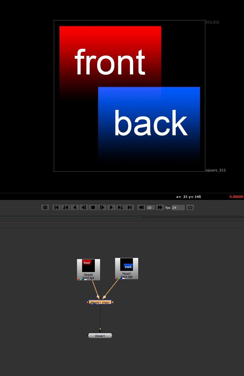
Over: The ‘3D Element’ Operation
This operation is specifically designed to layer a four-channel pre-multiplied image (such as most 3D renders) on top of another image.
Expressed mathematically an Over is…
O = A + [(1 – a) x B]
also expressed as…
O = A + B (1 – a)
O = output image
A = foreground pre-multiplied element
B = background plate
a = matte of A (alpha)
(1 – a) = inverted matte of A (alpha)

Write a description of this equation…
The foreground image (A), is a 4-channel pre-multiplied image meaning the alpha is included as part of the image and it is added to the second half of the equation.
The second half of the equation, the background uses the inverse of the pre-multiplied alpha from A, (1 – a), where the inverse operation reverses the alpha values and applies this to the background.
Then the foreground, a pre-multiplied image is added to the final value of the background operation. The inverse alpha of A has been applied to B and then the foreground is added to this value.
Because the background alpha is transparent where the foreground is opaque the foreground values will remain over the background looking like it is sitting over the background.
At the edges, if I have an alpha being applied to the rgb values coming through the A plug and have a value of 0.4 on the edge then 0.6 is the transparent. The calculation needs the opposite value in the background for them to fit, the alpha’s need to line up with the correct values.
This operation is for a 4-channel pre-multiplied image to be layered on top of another image. It assumes the A’s rgb channels have already been scaled by the matte and then the rest of the operation is the same as a keymix. Eric’s class notes, week 2.
Under: Inverse ‘Over’ Operation
Expressed mathematically an Under is…
O = A (1 – b) + B
or
O = [(1 – b) x A] + B
O = output image
A = foreground element
B = background plate
b = matte of B (alpha)
(1 – b) = inverted matte of B (alpha)

Write a description of this equation…
The inverse of over.
Takes the inverse values of B’s alpha or matte and multiplies with A resulting in A now being transparent where the original B’s alpha was 1. This causes A’s transparent values to match the background’s alpha (white).
When A is added to B the new transparent values in A show through the background.
It looks like B is cropping A, because the B’s alpha has been inverted and multiplied to A, it is using B’s alpha channel as a crop on A’s rgb.
A is scaled by the inverse matte of B then added to B.
In
This operation requires only a matte input for the B channel i.e.
O = Ab

Write a description of this equation…
The b is only a matte image (it an be a single-channel image or the alpha channel of a four-channel image), ignoring the colour channels.
The In operation uses the B’s alpha channel to crop A’s rgb’s. Where B’s matte is white I will see the A image and where B’s matte is black there will be no A image thus cropping the image with the matte. The black areas of B’s matte takes away the colour values of A’s image. When the pixel values of the A image are multiplied by 0 from the background matte the result will be 0, displaying an images from the foreground where the alpha has intersected between A and B.
It is described as A in B, the result is an image that consists of only the area in image A that is overlapped with the matte of image B. In sort A is scaled by the matte of B.
Out: Inverse ‘In’ Operation
Expressed mathematically…
O = A (1 – b)

Write a description of this equation…
The inverse mate of B where the original matte was white it is now black and where it was black it is now white. Now I would see the opposite of what I saw with the In operation. Where there was an image for the In operation it would now be black in that area and where it was black for the In operation there would now be an image.
The inverted matte of b, where there is now white I can see the foreground image in this area and the original pixel values are kept here and the black cancels the pixel values and the image is no longer seen in that area.
Described as A outside of B by using the inverse of B’s alpha channel to cut into A’s RGB, the final image consists only of pixels from A that did not overlap the matte of B. In short A is scaled by the inverse matte of B.
Mask
This operation requires only a matte input for the A channel i.e
O = aB

Write a description of this equation…
Using the alpha channel from A (a) where the value is 1 then the background shows through. As this is a multiplication where A’s alpha is 0 nothing will be displayed from B. It is only reading the colour information from B through the alpha of A.
It is said that B is masked with A’s Alpha. In short B is scaled by the matte of A.
Stencil
Expressed mathematically…
O = B (1 – a)

Write a description of this equation…
The background is multiplied by the inverted alpha from the foreground.
So where the foreground was originally 1 it is now black and when multiplied to the background it gives no pixel values. The background shows black in this area.
Where the foreground alpha was originally 0 it is now 1 and when multiplied to the pixel values of the background the original pixel values of the background are shown.
Atop
Expressed mathematically…
O = (A x b) + [(1 – a) x B]
or
O = Ab + B (1 – a)
O = output image
A = foreground element
B = background plate
a = matte of A
b = matte of B
(1 – a) = inverted matte of A
(A x b) = foreground scaled by background matte

Write a description of this equation…
Step One : A is multiplied by the background’s alpha. So where the backgrounds alpha is white we will see the foreground image.
Step Two: The inverse of the foreground alpha is multiplied by the background. Where A’s alpha was originally white it is now black and when multiplied with the backgrounds pixel values it cuts a hole in the background image where the original A’s alpha was white.
Step Three: The values from step one and step two are added together. Where the foreground is showing through in step one and the background showing through in step two we now see them as a combined image.
“This places a foreground over a background, but only in the area where the background has a matte.”
Brinkmann, Ron. The Art and Science of Digital Compositing: Techniques for Visual Effects, Animation and Motion Graphics. 2nd ed. Amsterdam ; Boston: Morgan Kaufmann Publishers/Elsevier, 2008. page 170-171.
Image Blending Expressions…
Note: Remember, Compositing Operations are expressions requiring the use of a matte. Image Blending expressions do not use mattes.
Multiply
Expressed mathematically…
O = A x B
O = output image
A = foreground image
B = background image

Used on its own this operation produces a dark result i.e. Multiplying with black leaves the result black. Multiply with white means the result is unchanged. Any number in-between will scale the final RGB result to a smaller number therefore the result is always darker.
Screen
Expressed mathematically…
O = 1 – [(1 – A) x (1 – B)]
O = output image
A = foreground image
B = background image
(1 – A) = inverse of A
(1 – B) = inverse of B

It is a multiplicative operator with an additional step of inverting both images before being multiplied. The result is always lighter. Dark areas in the background plate are brightened by lighter areas on the foreground image but bright areas in the background image are relatively unaffected by the foreground.
Plus
(a.k.a. Add or Linear Dodge)
Expressed mathematically…
O = A + B
O = output image
A = foreground image
B = background image
In short A is added to B.
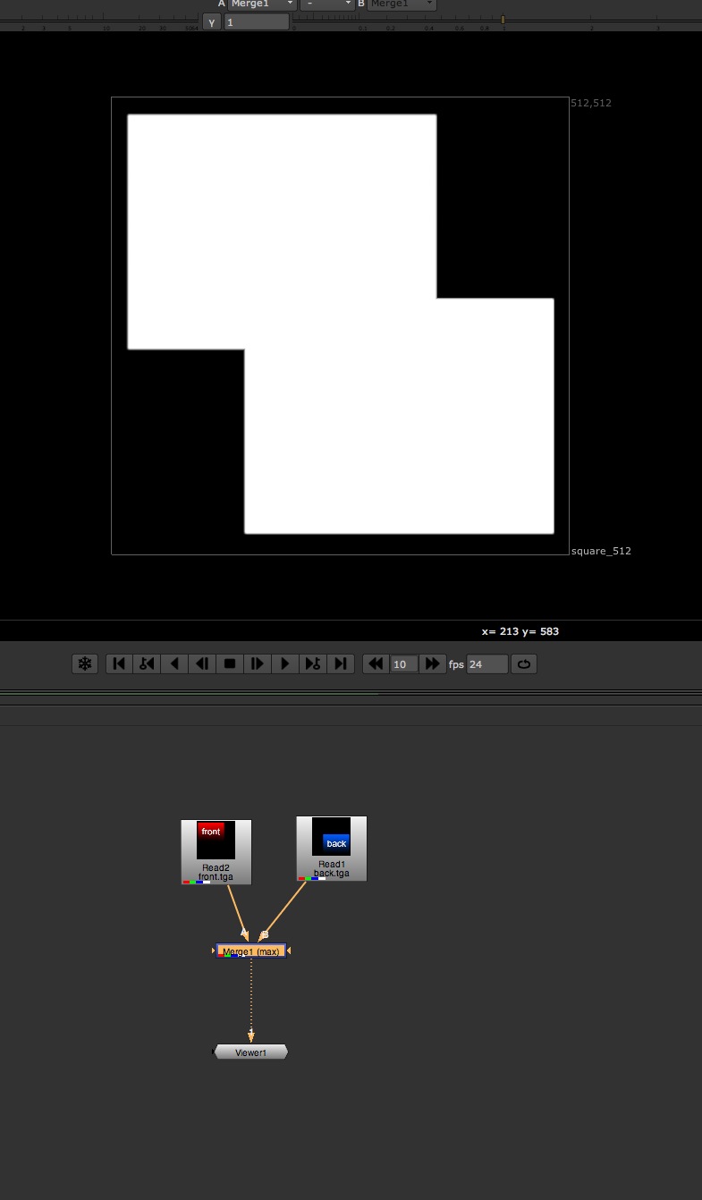
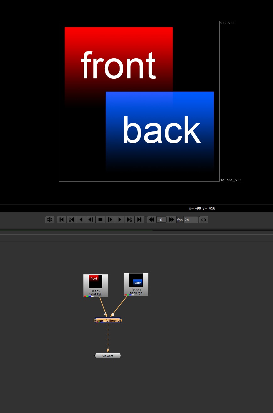
4. Maximum & Minimum

These operators combine two images and give the result that is the maximum pixel value of the two images being compared or conversely the minimum value. These are only useful when wanting to combine only the light or dark areas of two images.
ONES NOT COVERED YET
MAX (A,B)
DIFFERENCE (A-B)

A blend mode defines how the colours an object will interact with the colours behind it controlling how the colours react to the colours behind it.
My Notes
REFERENCES
Brinkmann, Ron. The Art and Science of Digital Compositing: Techniques for Visual Effects, Animation and Motion Graphics. 2nd ed. Amsterdam ; Boston: Morgan Kaufmann Publishers/Elsevier, 2008.
Lanier, Lee. Digital Compositing with Nuke. Waltham, MA: Focal Press, 2012.
Wright, Steve. Digital Compositing for Film and Video. 3rd ed. Focal Press Visual Effects and Animation Series. Amsterdam ; Boston: Elsevier/Focal Press, 2010.
http://opticalenquiry.com/nuke/index.php?title=Merge_Blend_Modes
SECOND YEAR EXAM
Question 1
a) Define what a ‘Compositing Operation’ is.
b) Define what an ‘Image Blending’ expression is.
c) Define what an ‘Alpha Channel’ is.
Question 2
Describe step-by-step what a ‘Keymix’ operation is and how it works.
Question 3
a) What is a ‘pre-multiplied image’?
b) What kind of image is typically ‘pre-multiplied’?
c) Why is a ‘pre-multiplied’ image a problem for a ‘Keymix’ operation? What would happen to the foreground element’s edge pixel?
d) Describe how an ‘Over’ Operation differs to a ‘Keymix’ as well as what characteristics they share.
Question 4
a) What problem can typically occur if you ‘colour’correct’ a ‘pre-multiplied image’?
b) How do you avoid this problem?
Question 5
a) What does Nuke’s colour management system do when reading in images with an sRGB colourspace? How does it perform this task?
b) Why is this necessary?
c) If ignored, what problem occurs when Nuke’s colour management system ‘reads in’ pre-multiplied images with an sRGB colorspace?
d) How do you resolve this problem?
e) What would you do in Nuke on a Read Node when ‘reading in’ a pre-multiplied image which has been rendered using a linear image file format?
Question 6
Describe two reasons for using multiple keys within a single keying solution.
Question 7
The diagram below represents the nodal hierarchy for the Plane comp exercise finished in class.
a) Fill in the names of the numbered nodes. Have not put the network on this post.
b) In the space provided below briefly outline the role of these blank nodes and their function within the script. The are six blank nodes.
Question 8
Draw a diagram which represents a nodal hierarchy incorporating TransformMasked nodes to ‘patch’ two areas of the same source footage.
Include…
a) A RotoPaint node for finessing the resulting patch
b) Tracker nodes in the hierarchy where you think they are required
Question 9
When rotoscoping hair using the RotoPaint node describe three steps involved in creating an appropriate brush stroke for the matte.
Question 10
a) When setting up your preferences for rotoscoping explain why you would want to increase the pick size and decrees the line width of you Bezier curve.
b) Describe how the placement and number of your Bezier points can either facilitate or hinder the animati process.
c) When rotoscoping, outline the methodology for ‘breaking down’ the animation of a Bezier curve.
d) Explain two reasons for using multiple Bezier curves for rotoscoping elements in an image.
