MOTION BUILDER – 3D character animation software. Capture, edit, and play back complex character animation in a highly responsive, interactive environment. Work with a display that’s optimized for both animators and directors.
ADVANCED SKELETON Advanced Skeleton can create rigs with unlimited body configurations, 3 heads, 5 legs, 100 fingers, & anything goes. Not only creatures, but you can also rig props, vehicles, and just about anything. You can at any time go from Advanced Skeleton, back to the Fit Skeleton, make changes, and rebuild.
ANIMATION MENTOR free animation rigs
NICO SANGHRAJKA: ON BRINGING DEADPOOL TO LIFE: Find out about how Nico Sanghrajka rigged anti-hero Deadpool, motorcycles that crash, and SUVs that explode!
RIGGING VIDEOS on TWITCH CultOfRig including Season00 Day 12 – Automated FK/IK Switch
Maya Monday: Free Rigs and Rigging Software
Rooster Teeth Artists, Gio Coutinho and Shrivas Shyamsundar share some Maya tips and techniques they use for the hit web series, RWBY.
Career Advice: Working as a Character Modeler and Facial Rigger at a Creative Studio
CG SPECTRUM
Free Tiger Animation Rig, developed by CG Spectrum mentors like Jeremy Chinn, 3D Modeller for Life of Pi, it’s a feature-film-quality resource you can download FREE if you’re looking to test your creature animation skills. Download the Tiger Rig here.
CG SOCIETY
Realtime Character Rigging by Perry Leijten
Get an in-depth look at realistic character rigging for games with technical artist Perry Leijten in this upcoming webinar event.
ROBOTS VS. HUMANS: A NOTE TO RIGGING ARTISTS FROM HAYDEN HELIN When planning any rigging, it is important to have enough reference to understand how something should move, and what kind of limitations it has. With mechs, there is not as much deformation as there would be in organic characters, but there are a lot more limitations on the range of motion. As a result, the design may have to be compromised for functionality. For example, a human arm has plenty of freedom in its mobility, however this also adds complexity because shoulders have so much more range. That makes it difficult to have it deform correctly and may even require working muscles.
BRINGING OKJA TO LIFE, WITH MARTIN L’ANTONMuch of the success can be attributed to the incredible VFX/animation work that transformed Okja into a lovable creature, and we had to make sure to find out more about how the artists behind the movement brought her to life. That being said, we’re thrilled to have touched base with Martin L’Anton, rigging artist from Vancouver, who worked on the rig of the film’s main creature, as well as most of the secondary creatures.
CHARACTER RIGGING TIPS BY PHUNG NHAT HUY
My name is Phung Nhat Huy (you can call me Huy), from Vietnam. I went to Lasalle College of the Arts in Singapore to study and graduated with a degree in Animation Art in 2014. Currently, I’m working as a senior rigger/TD in Omens studio, Singapore, and have been working in the animation industry for 3 years.
Basic Character Rigging
POLYWINK | FACIAL RIG on DEMAND
Here they are, all 12 of them! These Maya rigs are perfect for honing in on body mechanics and acting as you develop your character animation skills. They will work with Maya 2014 and up, and come with an AnimSchool Picker that can be mapped to any of the rigs by changing the namespace within the picker ui.
NOTES & HELPFUL INFORMATION
Rigging, the rigger builds the internal structure, the skeleton and creating controls the animator will use to bring the model to life by manipulating the three-dimensional object. A skeleton is the structure built into a 3D model that drives the geometry. Any time geometry needs to move skeletons can be used.
The joints and skeletons are based on hierarchies, parent or root joints with child joints moving under the parents. They can be grouped moving with the parent’s pivots point instead of their own. Forward Kinematics rotates directly at the top joint, rotation of the joints affects the position of the joints beneath it in the hierarchy, flowing down the hierarchy. Inverse Kinematics has an IK handle attached to the tip of the joint system and the joints in the chain are affected only by the IK handle. The animation flows up the hierarchy.
Skeletons make character animation easier often making the centre of gravity the pivot point.
It needs to be animator-friendly, efficient, robust and well- organised. It could be a character or a vehicle, firstly understanding what it is in reality, then considering how it needs to function, how it will be animated, how it works in a 3D CG environment and recreate the rig for the model to work efficiently.
No one method is necessarily better than another, first understand and then adapt.
Kinematics describes how joints can be moved to animate objects, not the cause and characters in 3D computer graphics. A branch of classical mechanics that describes the motion of points, bodies (objects), and systems of bodies (groups of objects) without considering the mass of each or the forces that caused the motion.
The organisation of the skeleton is hierarchical. Joints are the parents of the upper joints so that when these upper joints are moved or rotated, the lower joints follow.
FORWARD KINEMATICS (FK) refers to a situation in which each joint in the chain inherits the motion of its parent joint. Movement orients from the root joint travelling down the chain by using rotations creating smooth and naturally occurring arcs of motion. The lower joints move in response to the movements of the upper joints.
INVERSE KINEMATICS (IK) cause the joints in a chain to orient themselves based on the position of a goal known as the end effector. The joints in the chain orient themselves and are controlled using translation. The IK Handle tool is made especially for IK and is used to position the end effector. The joint chain being manipulated by the IK handle and calculated automatically from the IK handle up towards the root of the join chain. The joints are bent according to where the end effector is located. Need to let the IK Solver know which way the joints will bend – set preferred angle.
When a foot is placed on the ground, any movement in the pelvis area would move the foot out of place. IK solves this problem by controlling a series of joints using an IK handle. Moving either the handle or a parent joint evokes the IK solver, which calculates the appropriate joint rotation to achieve the desired pose.
IK can be used for many things such as butterfly tail, tentacles, fins, ropes, chains, whips, flutter flag, hair, ponytails, pump pistons.
- SINGLE CHAIN IK SOLVER provides IK in its simplest form. When moving the IK handle, the chain will update so that the joints like along a plane relative to the IK handle’s rotation. Could be used for a reverse foot setup. Can easily control the bending of a joint chain, does not give good control over the orientation of the chain eg using a Single Chain Ik on a character’s knee, the knees could easily spread outwards.
- ROTATE PLANE IK SOLVER gives more control and is the most commonly used IK solver. Can use the IK handle so that the joints lie along a plane and then rotate the plane using a twist attribute or by moving a pole vector handle. Could be used for a character’s arms and legs. Enable the ability to define the rotate plane vector, which runs between the start of the joint and the end effector. The rotate plane acts as the goal for all joint rotations. By default, the Ik handle will manipulate the joint chain so that it follows the default rotate plane. Then can rotate the plane by either editing a twist attribute or by moving a pole vector handle.
- SPLINE IK SOLVER gives control of the joint rotations using a spline curve. Either the chain can be moved along the curve or update the shape of the curve using its CVs. Could be used for character’s spines.
Pole Vectors – sometimes when manipulating IK handles, the solver can flip the joint solution by 180 degrees. Flipping occurs when the end effector is moved past the plane’s pole vector axis. To solve this issue move the pole vector handle out of the way. May need to set keys on the pole vector to control flipping during motion. To obtain easy access to the pole vector it can be constrained to an object then the Show Manipulator Tool does not need to be used to edit the pole vector location.
PREFERRED ANGLE is the default direction which needs to be set otherwise the solver will not be able to bend the joint. When setting the preferred angle the solver has a guideline to follow, telling the solver in which direction to bend. Stickiness setting which can be turned on/off in the Attribute Editor to plant the IK handle in one place. To adjust the Preferred Angle, select the joint > Attribute Editor in the Joint drop down. Can use IK and set up Preferred Angle values to give each joint priority so that they move one right after the other eg 20 and 15 for following Preferred Angles.
IK Priority of 1 is evaluated before a solver with priority 10 such as an IK solver in the had or fingers needs to be evaluated after the IK solver in the arm. The priority can be changed after the IK solver is created in the Attribute Editor under IK Handle Attributes. Can change multiple IK handles’ priority by selecting the IK handles and entering this MEL command. The autoPriority flag automatically prioritise the. selected IK handles based on their position in the hierarchy. ikHandle -edit -autoPriority;
IK/FK Blending of a skeleton chain is a way to control goal-oriented actions like a foot planting on the ground or a hand picking something up while simple actions like an arm swinging as a character walks are typically easier with FK animation. IK/FK blending makes it easy to seamlessly switch between Ik and FK controls of a skeleton chain. Making it possible to selectively choose the appropriate keyframing for special motions. The arm swinging to form an arc can be difficult to create using IK, preferring FK. In contrast, a character is climbing a ladder needing to fix the hands to the ladder would use IK.
Key > IK/FK Keys > Set IK/FK, Enable IK Solver, Connect to IK/FK, Move IK to FK. One way to switch, to blend between FK and IK is to select the IK Handle and turning the Enable IK Solver ON or OFF > Set IK/FK key. Can connect the IK/FK blend to a random object eg a cube using a Point Constraint > select both the cube and the IK Handle > Connect to IK/FK resulting in when the cube is selected we have the IK Solver enabled.
CLUSTERS & SET DRIVEN KEYS to drive muscle and therefore skin changes resulting from animating joints. Create a cluster from the selected vertices around the joint > display the Selection Handle > Parent the cluster to the joint > adjust the Deformation Order > use a Set Driven Key to influence the muscle shape during animation. Can not only use this method to apply changes to skin with clusters it can be used for other situation such as cloths, eyes, eyebrows. Weight values for vertices can be adjusted in the Component Editor. Attributes can be added using the Add Attribute window.
BLEND SHAPES can be used with Clusters to control expressions eg smiling, frowning. Select the vertices > create the Cluster > change the Deformation Order > parent to the same joint as the other clusters > adjust Weight values in the Component Editor. Can use many clusters to create expressions, consider expressions being asymmetrical.
Set Driven Keys (SDK) are keyframes that are driven by the attributes of another object rather than time, creating a relationship between any two attributes. When needing to control attributes based on the animation of another attribute. There is a driving object and a driven object or drive attributes on the same object. SDK is a curve relationship between two attributes. In the Graph Editor, the horizontal axis represents the driver attribute values and the vertical axis represents the driven attribute values. It is possible to adjust the tangents of this curve and add additional keys helping to achieve some interesting behaviour.
EULER ROTATION is calculated based on three angle values (X, Y and Z) plus the order in which the angles are calculated. Euler rotation is prone to the problem of Gimbal Lock, where two of the axes overlap and lead to the same result. The standard in Maya.
Rotate order is the order of operations which orientations are evaluated. The default is X, Y, Z and viewing in local space. Meaning Z carries both Y and X, Y carries X and X has no effect on the other two axes.
For the Spine set the orientation to XYZ so that the local rotation axis of the joints will be aligned in the direction of the spine. Setting the Secondary Axis World Orientation to +Y, the X-axis of the joint will always point towards the child joint and the Y-axis will point in the. world positive Y-axis direction.
GIMBAL LOCK is when two of the rotation axes are sitting on top of each other. The result is that both axes will produce a similar rotation result losing the ability to rotate on one of the axis.
Building relationships and creating hierarchies with parenting giving the child a new world centre, the parent and affecting all transform attributes. Group an object to itself, selecting only the object creating a group transform node and no group node. Constraints, instead of affecting hierarchical structure, create a constraint node that lies under the constrained (slave) object and only affect the defined attributes. Constraints also have weighting values to define how much influence the master object has over the slave object. This can also be used for control between multiple objects that have influence on a single object.
IK SPLINE allows the control of a chain of joints with a few control points. Keep the spline as simple as possible and for the most part, the default of four CVs works well. The curve created when setting up the Ik spline solver will attempt to stay as simple as possible by default. Create clusters for the CVs to make selecting and animating easier. Clusters have translate, rotate and scale attributes while CVs only have position attributes. Meaning that CVs cannot be keyframed as accurately as clusters.
The IK spline is not created from a root joint and as a rule not cross any branching joints to enable animating animation of different sections of skeletons individually eg if the spine chain is from the root joint it would rotate the back and hips when only needing to rotate the back or when needing to rotate the back and neck separately. The Twist attribute will rotate each of the joints in the solution around the X-axis, causing a twisting action. Moving CVs move in a serpentine manner. Spline IK handles cannot be translated the way other IK handles are.
ADDING ATTRIBUTES in the Script Editor to execute the addAttr MEL command.
addAttr -k l -ln middleCurl -at double -min 0 -max 10 -dv 0 leftFingesrManip;
Skinning the mesh to the joints allows us to deform the mesh for animation. It is a process of assigning how much influence a joint has over a vertex, therefore defining how the skeleton will deform the geometry.
IK SPLINE keep the spline curve as simple as possible for the IK spline. The default of
Some explanations from:
Amin, J., 2015. Beginner’s guide to character creation in Maya
Palamar, T., 2016. Mastering Autodesk Maya 2016
Rigging is not only people, it can be inanimate objects such as 18 wheel truck, trailer, tracks on a tank, paper bag, chip packet, book, roll of tape, wheelbarrow, tree, doors, guns, mechanical objects. Building artist friendly rigs, spending time with artists and understanding the needs of the team, listening and taking feedback. Learn scripting/coding. focus on deformation, showing you can deform a realistic character well with advanced mechanical and organic rigs. The use of Sin and Cos functions to rotate a point about another point, or make a point spin. If you want to make a bird or a plane then you will need to understand aerodynamics, effect particles then a need to understand physics and normals and so on. Remember you still need to skin meshes, set up cloth, hair, dynamic chains, transfer mocap etc.
2D ROTATION Example of a 2D rotation through an angle w where the coordinates x, y go into x’, y’. Note that w is positive for a counterclockwise rotation and that that rotation is about the origin (0, 0).
CONSTRAINTS
Are based on the pivots of objects and can blend keyframe animation with constraint animation. Offset allows for an offset in any axis otherwise the source assumes the exact orientation of the target and for multiple targets the source uses the average.
Constraints let you constrain the position, orientation, or scale of an object to other objects. Further, with constraints you can impose specific limits on objects and automate animation processes. Setting up relationships between objects, a direct relationship between the source and the target object’s Translate, Rotate and Scale attributes.
Point Constraint connection only the Translate attribute causing an object to move to and follow the position of an object, or the average position of several objects. The weight slider in the option box can create more of an influence on the source by any of the targets. This is useful for having an object match the motion of other objects. Point constraint is used to make one object move according to another object. You can also use a point constraint to animate one object to follow a series of objects. The constraint on the Translate leaves the Rotations free to be animated.
Point on Poly Constraint attaches a source object to a vertex of a mesh, snapped to the vertex of the target at its pivot point such as a button on a jacket, leaf on a tree.
Aim Constraint constrains an object’s orientation so that the object aims at other objects. Adjusts the source’s rotations so that the source always points to the target object. Specify which axis of the source is to pint to the target using the Aim Vector which specifies which axis of the source is the “front” and points to the target and Up Vector settings which specify which way the object faces when pointing to the target. Typical uses of the aim constraint include aiming a light or camera at an object or group of objects. In character setup, a typical use of an aim constraint is to set up a locator that controls eyeball movement.
Orient Constraint connects the Rotate attribute and is used to make one object rotate according to another object. An orient constraint could be set on a wrist manipulator to control rotation of the hand, drive the rotation of wheels.
Scale Constraint matches the Scale attribute of one object to the Scale attribute one or more other objects being useful for keeping objects the same size.
Parent Constraint is used to make one object behave as if it was parented to another object, constraining the Translation and Rotation attributes., mimicking a parent-child relationship keeping the objects aligned without grouping issues. A parent constraint will be used to constrain the clavicle to a manipulator.
Geometry Constraint restricts an object’s pivot to a NURBS surface, NURBS curve, subdivision surface or polygonal surface, restrained to the surface of the target object. Attaching at the pivot point to the surface of the target, shifting as the target surface changes. Can be used when wanting to keep an object on a deforming surface. Constrains the location of the source to the target, a Normal Constraint’s Aim Vector specifies which way is up for the object, it orientation.
Normal Constraint keeps an object’s orientation so that it aligns with the normal vectors of a NURBS or polygonal surface, restrained to the surface of the target object. Using a Normal Constraint rotates the object to follow the surface’s normal, keepign it perpendicular to the surface. A Surface Normal is an imaginary perpendicular tangent line that emanates fro all surfaces to give the surface a direction. The Aim Vector specifies which way is up for the object, its orientation the setting does not constrain the location of the source to the target, for this consider a Geometry Constraint.
Tangent Constraint keeps an object moving along and oriented to a curve, points along a curve’s direction The curve provides the path of the object’s motion and the object orients itself to point along the curve.
Pole Vector Constraints always points an IK’s pole vector to the specified object. A pole vector constraint will be used to control the rotations of the arms, providing a visual aid for positioning the elbows. Can be used to control twisting when joints are constrained to locators, to keep Ik joints from flipping beyond 180 degrees of motion.
Other types of constraints: Point on Poly, Closest Point.
Maintain Offset option for constraints ON will make sure the joint stays with its current rotation instead of snapping to the controller’s rotation when being constrained eg LeftHand Joint orient constraint to the Controller.
Pivot Point locations can affect movements when objects are constrained to joints to control movement.
Change normal constraint target object weights
Each constraint has at least one weight attribute, there can be multiple weight attributes that determine the percentage of weight coming from the target object. The weight attribute is usually labeled with the name of the target object followed by the weight index eg WO.
In the Channel Box with the constraint highlighted the Interp Type attribute can be either Shortest, Longest or No Flip if blending between targets has interpolation issues. Also consider setting the Slide Control WO attribute to 0.5 on each of the two.
Constraints can be set up between two objects, constrained simultaneously to tow objects. The values can be changed in the Channel Box between 1 and 0. Using the Add Attribute window a new attribute is added to the Channel Box where the values between 1 and 0 can be changed to control the constraint between the two objects.
SET DRIVEN KEY
With the Set Driven Key window, you can link objects so that one object’s attributes can drive or dictate the attributes of another object. Cannot use movements other than indicated by a Set Driven Key. A Set Driven Key establishes a relationship for objects allowing for the creation of controls that drive certain features.
By setting extra attributes then attaching them to a character or an object the new attributes drive parts of the animation sicj as connecting the Translate attribute of the driver to the Rotate attribute of the driven. Other examples could be Eye Movements, Animating Stretch & Squash, Finger Movements.
CUSTOM ATTRIBUTES Add Attribute
You can add dynamic custom attributes to your node. Some applications include:
- Link attributes so that one attribute drives another; for example, in a rig
- Add a custom attribute to an object and use it in an expression; in particular, to control a combination of other attributes
- Add a custom attribute to a particle shape node to control its value in an expression
- Use a custom attribute as a variable to store a value temporarily to be read by other attributes
Can include groups of attributes such as eye movements and a tail stretch.
LAYERS
Where objects in a scene can be organised to show, hide or edit them all at once. Layers give the option to create and blend multiple levels of animation in a scene. Creating layers to organise new keyframe animation or to keyframe on top of existing animation without overwriting the original curves.
NAMING JOINTS
- Mirror Joints and Rename: Skeleton > Mirror Joint > Options > Mirror Across to YZ, Search For to Left, Replace With to Right > Mirror.
- Select > Hierarchy > locate the Field Entry at the top right of the main interface and change its setting to Rename > type eg LeftHandIndex in the Field Entry > Enter. The selected joints are renamed 1, 2, 3 etc.
- After Mirroring joints select in the Outliner and in the MEL command line enter the following to rename joints automatically…… for($each in
ls -sl) rename $eachsubstitute "Left" $each "Right"; SCRIPT
When the joints were created with Auto Orient set to SYZ if an axis is flipped it needs to be rotated by 180 degrees on the X-axis. Enter a simple MEL script in the Command Line.
rotate -r -os 180 0 0
Maya assigns orientation based on child joint orientation. Knowing this helps predict where a flip of local rotation may occur.
BASIC SKELETON
- neck, for side to side and turning
- shoulder, for movement that includes the chest
- hand, for all the joints and wrist for bending, twisting and twisting to including the entire arm
- leg
- face, include the teeth
- connect joints eg arm, leg
- mirror copy, something to consider is aligning the local axes to each of the joints of the skeleton. The default options for the first joint then its local axis will be aligned automatically to the next joint. The X-axis automatically aligns to the next joint with the last joint, because there are no more joints, aligns to the absolute axis of the window.
SOME SIMPLE EXPRESSIONS for CHARACTER ANIMATION
In the Expression Editor – BodyFront:
Body.tz = (L_Foot.tz + R_Foot.tz)/2;
Body.tx = (L_Foot.tx + R_Foot.tx)/2;
Body.ry = -(L_Foot.ry + R_Foot.ry)/2;
Means the addition of the lengths of both the right and left leg deivied by 2 is the Translate Z and X of the body. The body node always located between the left and right legs. The “-” represents rotation in opposite directions.
In the Expression Editor – BodyUP:
Body.ty = (L_Foot.ty + R_Foot.ty)/2;
This formula controls the movement of the body along the Y-axis.
To stop the expression being used in some areas select in the Channel Box and set from Normal to Blocking then to establish the expression, constraint again key in the Channel Box from Blocking on one frame and on the next key to Normal.
The Channel Control window has a list of Nonkeyable Hidden and Nonkeyable Displayed for the selected.
ROTATIONS
Maya calculates the object’s rotations between keys by interpolating the rotation values from one key to the next. There are two methods: Euler, Maya’s default and Quaternion.
EULER ANGLES Maya uses Euler angles to determine the object’s axis-specific orientations over time, using three separate angles representing rotations about the X, Y and Z axes and an order of rotation. The rotation order specifies the order in which the animation object is rotated about its X, Y and Z axis, Maya default being XYZ.
Independent Euler curves, interpolation is calculated from key to key on each individual curve, independent of their neighbouring rotation curves. Use when keyframing a single rotation channel or need to additional keyframes to a single rotation curve.
Synchronised Euler curves are locked together in time with interpolation being calculated from key to key on all of its rotation curves simultaneously. Use when keyframing multiple rotation channels, or needing to add additional keyframes to all the rotation curves of an animated object.
Moving a key in time on an independent Euler Rotate X curve moves only the key on the Rotate X curve. Moving a key in time on a synchronised Euler Rotate X curve will also move the corresponding keys on the Y and Z curves.
Euler angles interpolate animated rotations of an object’s orientation its individual axes is evaluated one axis at a time making it prone to artifacts such as gimbal lock and flipping. Gimbal lock occurs when rotations about a single axis causes unwanted rotations or become coincident. Flipping occurs when angles unexpectedly wrap around positive or negative 180 degrees during Euler-angle rotations interpolation between frames.
Quaternions provide smooth interpolation, storing the overall orientation of an object, rather than a series of individual rotations. Storing only orientation values, can be used to calculate the shortest rotation from one orientation to another. Maya first stores the keyed orientation values as Euler angles, converts them to Quaternions for interpolation, then converts the interpolated Quaternion rotation values back to Euler angles for display.
Quaternion curves do not have tangency control. They are created as linear or step type interpolations only.
- Independent Euler-Angle Curves
- Synchronised Euler-Angle Curves
- Synchronised Quaternion Curves
Rotating Objects Using Quaternions
Animated rotation in Maya
TRUE QUATERNION TWISTING WITHOUT FLIPPING IN MAYA
CHARACTER SETS
A collection of attributes that can be animated simultaneously by combining attributes in one Character Node to display all the attributes in the Channel Box for keyframing and can apply a Set Key that will key all the attributes within the set.
ARTSTATION FACIAL ANATOMY
SHAPES, SKINNING and BINDING
Bound geometry points (CVs, vertices, lattice points) can be thought of as skin points. Set all transformations to default (Freeze Transforms) and check the model does not have any unnecessary history before Binding. Binding involves attaching clusters or groups of vertices or CVs of the geometry to the skeleton to allow the skeleton to deform the model. When joints move the section of the model that is attached follows, pulling with it the points that are attached.
BINDING POSE is the shape the model takes upon first binding to the skeleton and directly affects character movement. The position of the joints will play an important role in surface transformations.
MAX INFLUENCE VALUE is the one that determines the number of joints that will have influence on an individual skin point, how many joints will control the CVs and vertices, the influence on an individual skin point. Setting the Max Influences to 5 means that each skin point will no have more than 5 joints affecting it. The Max Influence can also be adjusted after the character has been skinned, except the new setting takes effect only on selected surfaces instead of the entire character with multiple surfaces.
- Rigid Binding (Maya’s first binding environment) where a skin point is fully assigned to a particular joint. The CVs and vertices are affected by only one joint. One advantage of Rigid Bind is the use of Flexors. When binding in Maya, the points, due to the option configurations, are bound to the adjacent joint, based on average values. Manually modifying CV Weight values for each joint for more precision and proper movement using the Component Editor, Paint Cluster Weight Tool, Lattice and Flexors. Edit Lattice points using the Edit Membership Tool, Component Editor and Lattice Flexor.
- Smooth Binding allows the skin points to be weighted across many different joints. The user can decide how many joints will affect the CVs and vertices. Does not use flexors. Change the influence of the weights between the joints having a total weight of 1.0 and can be shared between many different joints and influences. The weight or participation of a skin point’s influences can be locked or held to a specific value, inhibiting the weight from changing as adjacent skin weights are adjusted and a total value of 1.0 is maintained. Paint Skin Weight Tool to quickly and easily modify the Weight value as points are influenced by multiple joints adjusting how much influence is exerted by joints on the same points, for more detailed modifications use the Component Editor. Black will not influence, weights must be normalised and the influence will be shifted to other joints. Painting weights on a polygonal mesh is painting using UVs. Does not use Flexors. Weight values can be mirrored and exported, skeleton’s hierarchy structure and joint must be the same and the surfaces must have the same UV-axis because the Weight values are made into a black and white image file. Close Joint binds the skeleton based on its class structure, affected by the adjacent skin point. Closest Distance ignores the skeleton structure and binds the joints, first, to the nearest point. Max Influences specifies the number of joints. Dropoff Rate determines how the skin points will be affected by each joint. Prune Skin Weights will delete weights below a specific value.
- Interactive Skin Bind is almost the same os Smooth Bind giving similar results with the editing of the influences being slightly different. Only recognises a single mesh. A volume manipulators is created for each bound joint to adjust weights. When you have completed the rough adjustment of the manipulators to establish your initial weights, you can go on to paint weights and refine the deformation effects for the skin.
NORMALIZATION the greatest difference between Smooth and Rigid Bind is that in Smooth Bind one skin point can be influenced by all the joints. Maya automatically sets the sum of all Weight values to 1. To be greater than 1, Disable Weight Normalisation. To bring back the value to 1 use Enable Weight Normalization or Normalize Weight to change the value back to 1.
ALPHA an opacity value
LUMINANCE a brightness value eg for weight value to be exported
MAP SIZE X, Y determines the resolution eg 512
ASPECT RATIO to match the map to be exported
IMAGE FORMAT eg jpeg
Closest In History specifies that joint influence is based on the skeleton’s hierarchy can prevent inappropriate joint influences eg preventing a right leg joint influencing nearby skin points on the left let.
Dropoff Rates is another way to determine how each skin point will be influenced by different joints, determining how much the weighting decreases as the distance between the influences and the skin points increases. controlling how rapidly the influence of each joint on individual skin points are going to decrease with the distance between the two. The greater the dropoff, the more rapid the decrease in influence with distance. The Dropoff Rate can be adjusted on individual joints after the character is skinned. Increasing the Dropoff Rate helps localise the weighting for selected joints.
CLUSTERS and INFLUENCER OBJECTS movement in the skin caused by the flexing and releasing of muscles is not necessarily related to motion, this can be produced using Influence Objects or Clusters. The more clusters there are the more detailed and elaborate the movements will be. Skin cluster nodes are created for each of the surfaces that are bound to the skeleton when a character is bound. The skin cluster holds all the skin points’ weights and influences, the assignment of each point can be edited to different joints to achieve better deformations.
DEFORMATION ORDER When you use more than one deformer to deform an object, the final effect of the deformations can vary depending on the order in which the deformations occur. By default, the deformations occur in the order that the deformers were created for the object. The deformer created first deforms the object first, and the deformer created last deforms the object last. However, you can change or re-order the deformation order to get the effect you want.
Deformations are executed sequentially, before achieving the final deformation of a piece of geometry. Blend Shapes > Skinning > Jiggle > Sculptor Deforming the surface. It is possible to switch the deformation order, putting the Twick Node on top of the SkinCluster. Note the Tweak, Time and Disk Cache are Maya related nodes that are not to be reordered.
BLEND SHAPE is a powerful deformer that allows the blending of several target shapes onto a base shape. It is a good method to use to create perfect transformations. The deformer calculates the differences between the base and target shapes in percentages between 0 and 1. Blend shapes can also be used with drive keys. The node has one attribute for each of the target shapes that can be animated.
Blend shapes are usually used for facial expressions with the mouth, cheeks, jaw, eyes, eyebrows, nose, facial expressions, collisions with the face, creating additional shapes such as muscles bulging or swallowing.
The blend shape deformer has the ability to have in-between targets. There can be multiple target shapes in the same blend shape attribute. It is said to be in series and the in-between shape transition will occur in the order in which it is added to the target shapes.
Some basic phonemes used in the English language, even a character that does not speak would have facial expressions:
- A such as alright autumn and car
- E such as he tree and believe
- O such as like, flow, go and toy
- U such as like you, stew and noodle
- V and F such as like very and fabulous
- B, M and P such as like big, mat and put
- ah – by rotating the joint of the lower jaw
- e – lips become wider while the chin remains still
- woo – lips become pursed and rounded, back teeth cause the lips to protrude, no movement in the chin
- eh – basically the same as for the ‘e’ with the upper lip moving down slightly though not being so important
- oh – like the ‘woo’ sound
Mouth Shapes: jawDown smile, blowCheeks
Eyebrows: leftBrowUp, leftBrowSad, leftBrowMad, leftBrowUp
Eyes: leftWideOpen, leftLowerLidUp, leftBlinkMid, leftBlinkMax
Others: breath
An important thing in setting a Weight value is that a great number of vertices must move to create a natural expression. In reality, the action of opening the mouth uses all the muscles of the face. In order to create the full effect of opening the mouth, the configuration must be made to affect the sides of the nose, the muscles of the cheek and the bottoms of the eyes and ears. Also, in animation, it is a good idea to exaggerate the muscle movement so that almost all of the muscles of the face are affected.
In Smooth Bind, unlike Rigid Bind, the vertices are affected by all of the joints. Because it is simply the Weight value that determines how the joint affects the vertex. When adjusting the Weight value, Maya, in order to maintain the average value of 1, automatically raises the values of other joints. Modify the Weight value in the Component Editor.
Our facial expressions are determined by the muscles include the wrinkles in our skin, our teeth and our eyebrows.
Blend Shapes to cover all kinds of expressions and pronunciations and clusters such as for the corners of the mouth and tighten the mouth.
IN-BETEEN SHAPES
Can have multiple target shapes placed one after the other in the same blend shape attribute with the in-between shape transitions occur in the order in which they are added – to be in a series. When the blend shape node is created, it lists all the vertices of the geometry in order to bend them, even if the vertices would never be affected by the deformer. In-between targets can refine the deformation for complex blends and can edit a deformer set. Can edit the deformer set to remove any vertices that will not be moved by any of the tangents. Can create as may target shapes as needed to control a base shape.
PAINTING SKIN WEIGHTS refines the binding to improve skinning. When painting weights a Paint Weights Value of 0.0 is telling Maya to remove any weight coming from this bone and to reassign the removed weights to other bones already influencing this area. As a general workflow, remove weights when roughing out the weights on the entire character then start refining the influences by adding weights.
Pruning small weights will reassign weight from all the influences that are below a specified threshold.
Toggle Hold Weight to lock the weights for that influence, when Maya cannot find an unlocked influence to put weight on, it might end up adding it to unwanted places.
Point Scale Operation at a value of 0.9 will remove 10% of teh weight of teh selected influences and redistribute it proportionately among the other influences.
Numeric Weighting to check if there are weights from different and perhaps unwanted influences.
Adjusting the Max Influences means that a total of selected influences can participate in the weighting on a given skin point. The weighting of one skin point has a rippling effect on the weights of the other skin point. Consider lowering the Max Influences of each surface to help localise the control of the weighting.
Equalise Weights on Multiple Surfaces is to set the same weighting value on two surfaces to get a uniform weight across a seam.
Using Wrap Deformer can greatly simplify the weighting process since there is only a single poly object to bind and weight.
Toggle Hold Weights On and Off a hold flag for each influence objects locking the value helping prevent the new influence object from disrupting your existing weighting.
Flood Values there can be many joints affecting the same skin point, it maybe easier to select the surfaces and an influence and Replace all weighting values with a common value using the Flood button. This is particularly useful for removing unwanted weighting.
Prune Small Weights where a small amount of weight maybe added to many different influences. When taking a weight away from a surface, the weight gets distributed to every surface that has an influence on it.
Copy Skin Weights such as weighting a lower resolution model and copy the skin weights to a higher resolution model.
Import and Export Skin Weights generates one grey scale image per influence object and write it to disk. The images exported are relative to the model’s UVs, the model needs proper UVs so overlapping UVs might give importing the weight maps undesirable results. To transfer Skin Weights based on spatial location rather than UVs use Copy Skin Weights. When Copy Skin Weights, the source and target skinned geometry do not need to have the same UVs.
SCRIPTS
When the joints were created with Auto Orient set to SYZ if an axis is flipped it needs to be rotated by 180 degrees on the X-axis. Enter a simple MEL script in the Command Line.
rotate -r -os 180 0 0
Maya assigns orientation based on child joint orientation. Knowing this helps predict where a flip of local rotation may occur.
select skinCluster -q -inf meeper:
This Command tells Maya to select all the joints that influence the geometry.
for ($each in `ls -sl`)
{
setAttr -k 0 ($each + “.tx”);
setAttr -k 0 ($each + “.ty”);
setAttr -k 0 ($each + “.tz”);
setAttr -l 1 ($each + “.tx”);
setAttr -l 1 ($each + “.ty”);
setAttr -l 1 ($each + “.tz”);
}
To lock and hide the translation attributes for all selected nodes
PROCESS DIARY
3D RIGGING PROCESS DIARY, Part II
TUTORIAL ON ARM BROKEN HIERARCHY
Research and development I have undertaken into 3D rigging during the second part of my Rigging Studio 1 subject.
This is a tutorial for a broken hierarchy character rigging system describing how to construct an FK Arm control module and an IK Arm control module, including how they are integrated with a bind skeleton with IK/FK switching functionality.
Why are we using the FK and IK modules for the arms, what is their purpose? Our arms have different movements where they can either move freely or when touching something the movement is from the point of contact back up the body. The rig modules will be kept separate from the bind rig and the animator will have the ability to switch between these movements and incorporate them into the character’s movements.
Rigging uses Forward Kinematics or FK and Inverse Kinematics or IK to allow for this change in movement.
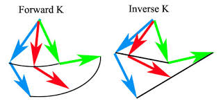
“FK rotates the bones directly at their top joint to assume poses.”
“The rotation of a joint affects the position of the bones and joints beneath it in the hierarchy. If you rotate the hip up, the knee and ankle swing up as if the character is kicking”
Derakhshani, Dariush. Introducing Autodesk Maya 2013. 9th ed. Indianapolis, Ind: John Wiley & Sons, 2012. page 394
“IK uses a more complex, but often easier, system of IK handles that are attached to the tip of a joint system. The corresponding base of the IK system is attached farther up the skeleton hierarchy to a joint determined to be the root of the IK segment. It need not be the root joint of the entire skeleton, though. The bones and joints in the IK chain are affected only by movement of the IK handle. When the handle moves, an IK solver figures out how to rotate all the joints to accommodate the new position of the IK handle. Moving an IK handle causes the bones to rotate around their joints to accommodate a new position.”
“Moving your hand causes the bones in your arm to rotate around the shoulder, elbow and wrist.”
“…..the animation flows up the hierarchy and is therefore called inverse kinematics.”
Derakhshani, Dariush. Introducing Autodesk Maya 2013. 9th ed. Indianapolis, Ind: John Wiley & Sons, 2012. page 395
The modular rig is not about transferring the control systems, the modules are independent of the bind skeleton, controls are not being mixed together. The only values that are transferred to the bind joints are the values of the joints themselves not the control systems, thus being integrated by transferring the end result of the joint’s movement into the bind skeleton. There can be many module systems, it does not matter how they are made, it is all about transferring the rotate values of one set of joints to the rotate values of another set of joints.
It is about setting up two different sets of controls for the arms, having different sets of joints that are controlling the system in a particular way when they are connected. They are linked to the original bind skeleton by connecting the rotate values of one set of joints to the rotate values of another set of joints, the input values to the bind skeleton. This is how the FK and the IK control rig systems will drive the bind skeleton, allowing the animator to blend between the arm modules with a switch. The controls can transfer from one system to another without popping, flipping or spinning.
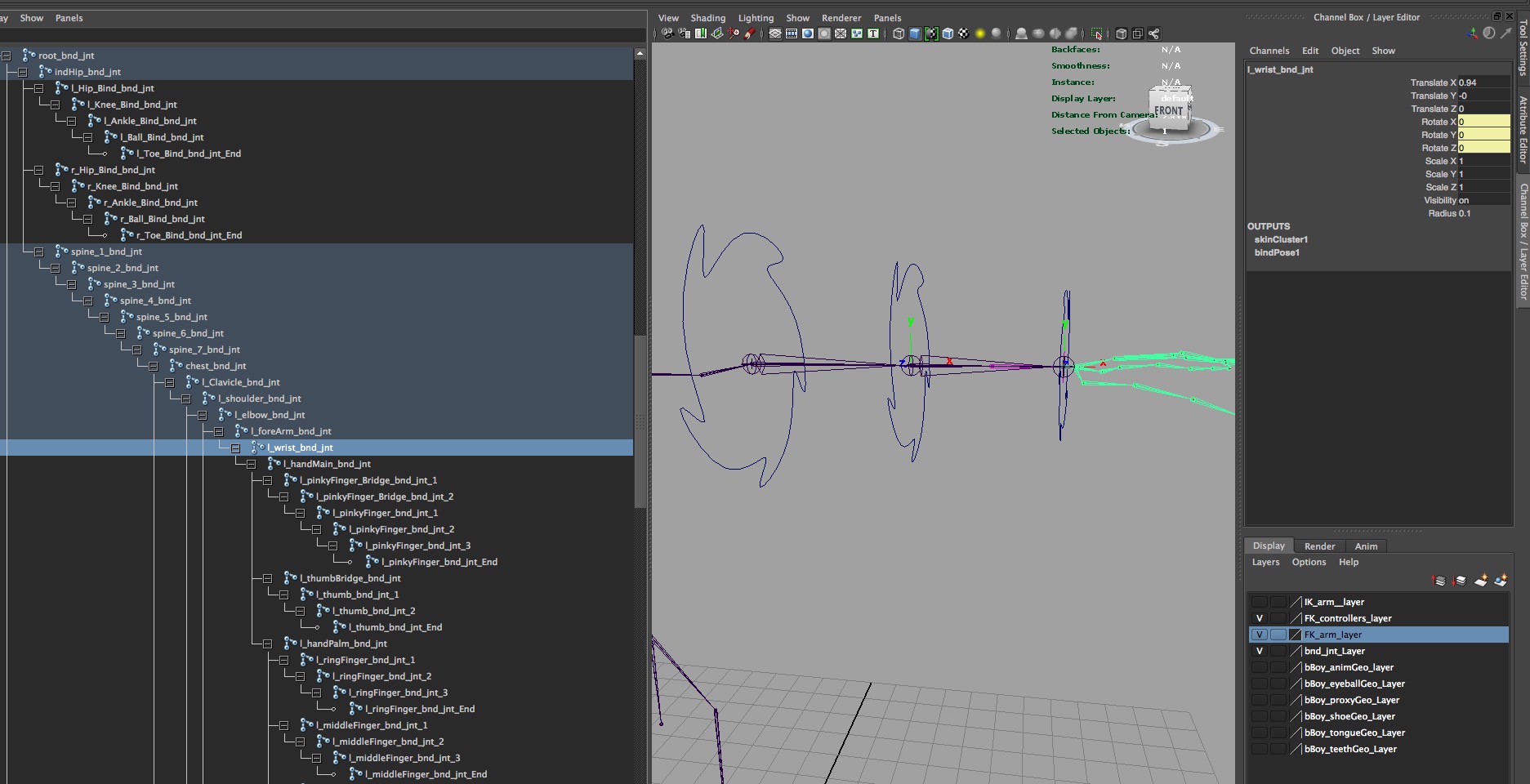
SETTING UP THE BIND SKELETON
The bind skeleton has been built by connecting joints in a hierarchically system with each joint’s default orientation being aligned with its bone. The x-axis of the rotation is aimed along the length of the joint, pointing down toward the child joint.
Before binding the geometry to the rig we need to consider a couple of things because what is chosen now with the orientation will affect how the weights are painted around these areas. We can change the rotate order after binding, the orientation does matter before binding. Joint orientation contains information about the direction and angle of the X, Y and Z axis and the range of motion.
Firstly we are looking at the orientation of the clavicle. The default orientation of this joint is not giving the motion that is required from the shoulders, it is not ideal for the up and down and the forward and backward motions of the shoulder. When using the orient tool it always relates to something, their parent, world, hierarchy and will not give us the custom movement the joint needs.
The rigged shoulder does not working the same way as the shoulder in our bodies, there are multiple influences in the body, the muscles are pulling in different ways. In a rig we are not using muscles to drive the bones and the custom orientation will help to simulate that part of the body by giving a more natural movement.
We can set up a custom orientation of the clavicle joint by slightly offset it to give a motion that relates better to the way we move the shoulder. It is manually changing the default orientation. There is not a value here, there will be an offset which we cannot copy, we need to pay attention to be able to do the same on the other clavicle joint. What is the joint going to be used for in the finished rig? Will something be plugged into it as part of the multi-module rig? Using broken hierarchies means having multiple skeletons, separate pieces that can control different joints. When multiple things control the joints they need the same orientations. It is not using this joint to connect multiple systems.

Orientation from the top view as the default and custom joint orientation. The bottom image is a front view of the custom orientation.
To adjust custom orientation before binding
- go to component mode
- select the question mark and choose local rotation axis
- set the rotation tool to local rotation, will not work in Gimbal
Another area of the arm that need consideration before binding is the wrist and the action of the forearm. There is a clear twisting action with the wrist that is being driven by the twisting of the forearm, in fact the wrist is not doing the twisting. Again in our bodies the muscles are responsible for the twisting and with our rig and the bind there are no muscles.
This has been achieved by including an extra joint on the bind skeleton, the foreArm between the elbow and the wrist joints. When looking at how the wrist works the wrist and forearm rotate at different rates, independently of each other or what could be called a graded twist. If the wrist is twisted 90 deg then the forearm needs to twist 45 deg. How can this be automated?
There are several ways this can be considered and we looked at the following:
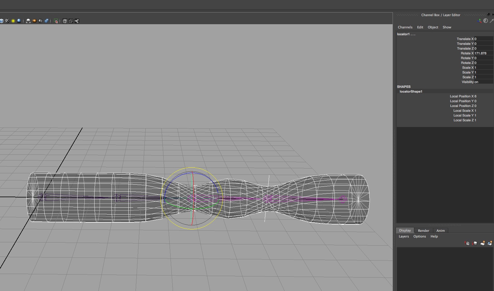
- Using two locator controllers to control the orientation of the joints, one for the wrist and one for the
 forearm. When it is rotated the child is not left behind, the hierarchy is overriding the rotation from the controller. This rotation will also affect the bound skin, a double twist. If they are rotated separately then they work like a hierarchy and not really doing the graded twist.
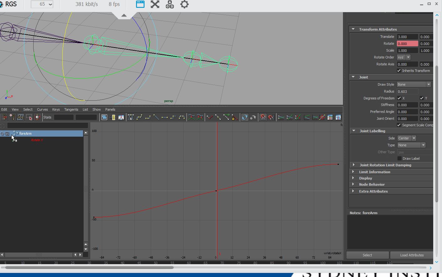
- Set Driven Keys using the Wrist as the driver and the forearm as the driven and working off Rotate X.
 This can be set up so when the Wrist is rotated 90 deg the forearm will rotate 45 deg. The problem arises when needing to go to the Graph Editor to adjust the tangents and these other factors come into the calculations. It is cumbersome and a potential problem when animating. Also what is the hierarchy doing? When I rotate, it is back with cyclic error potential, an infinite loop with the wrist telling the forearm to rotate and then the forearm telling the wrist to rotate. There is a curve in-between the two set driven keys which is affecting the calculations.
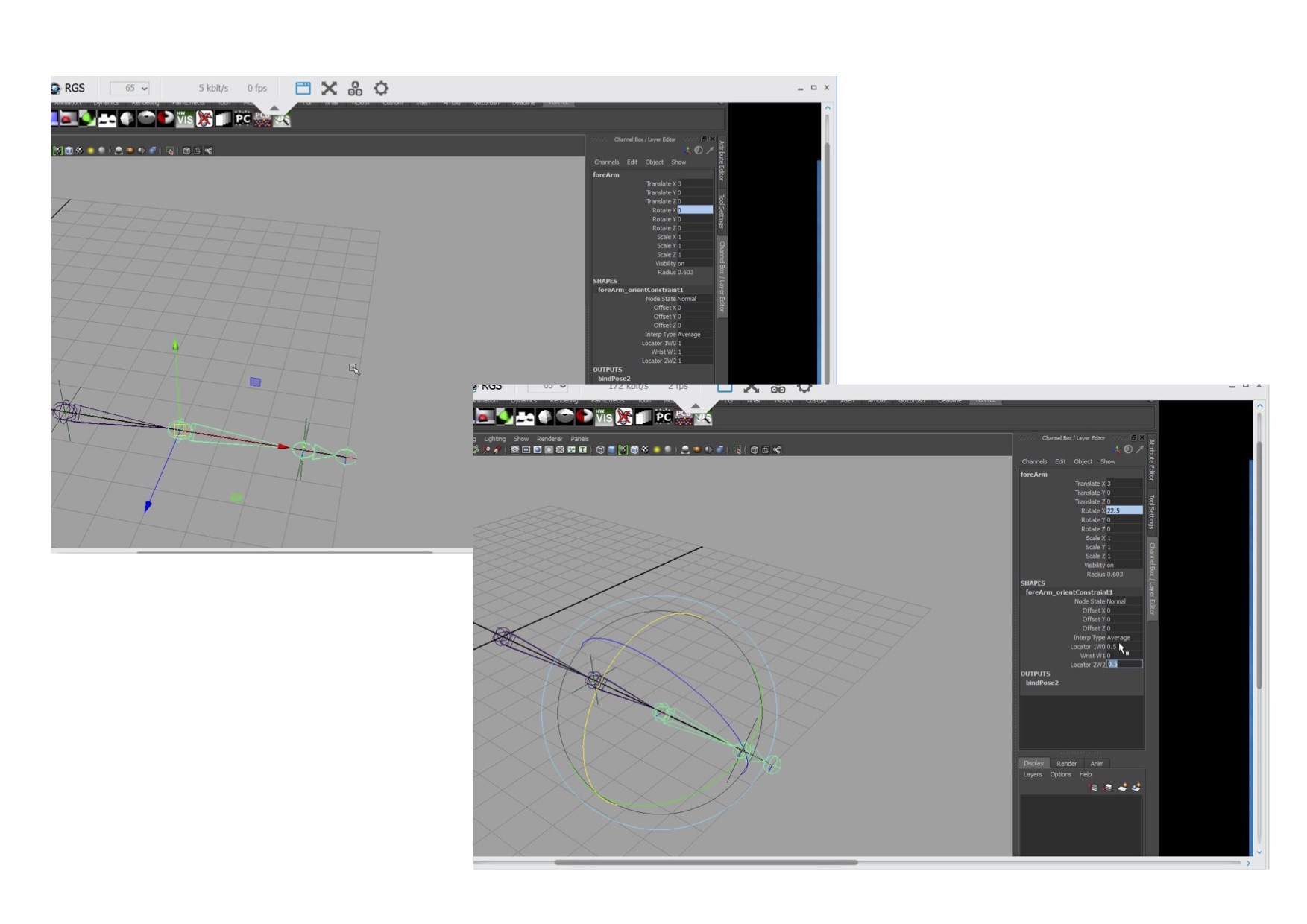
- If there is a controller with an Orient Constraint to the wrist and forearm telling them both to rotate, there is still the cyclic error problem and they are both rotating at the same rate. Adding another controller to tell the forearm twist, what to do, there are two weights in the Orient Constraint which will split the input which is averaged down to 1. Could adjusted to 0.4 and 0.6, though still getting the cyclic error using things inside the hierarchy. Constraints have flipping issues because of using the shortest path.
- Another option that is considered is Blended Constraints, it needs an expression to affect the
 influence. An expression is not the best option because when running an expression it can slow down the process, especial when the rigs become more complicated. foreArm.rx=loctaor1.rx/2. It does work as the locator has nothing to do with the Wrist rotation, it is influencing the forearm joint via the script, bypassing the cyclic error issue and giving half the rotation to the forearm. Can then use an Orient Constraint directly to the wrist.
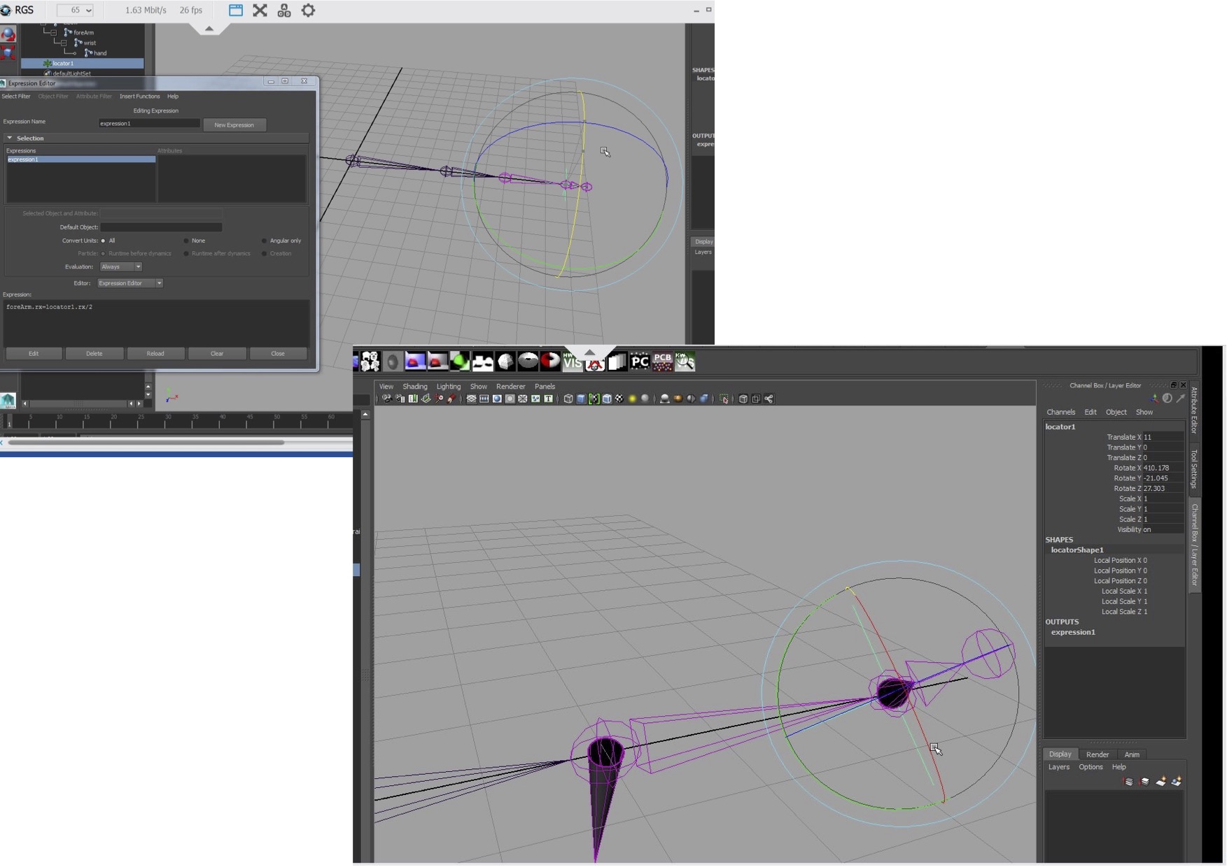
This is leading to the solution that was used. Instead of using the expression Maya has a multiplyDivide Node that does this. This gives a solution that is stable by controlling the forearm and wrist outside the hierarchy and independently of each other. The same controller is driving them independently. This is how it is set up.
- create a locator and rename l_wrist_loc, V snap to the left wrist, freeze the transforms and scale to 0.2. The locator has this custom scale as it does not have a proper shape node.
- duplicate the locator, snap to the right wrist and repeat the above
- buffer group for each locator to take the values, name it r_loc_buffer.
- the right side has different orientations, move the buffer group Pivot Point to the wrist joint before changing the orientation of the buffer group to match the joint. Do the same on the left side so they are consistent and match, even though the orientations are not an issue here.
- select the joint then select the locator buffer group and Parent Constraint with maintain offset off and delete the constraint. Could use the Right Hand Rule thought the constraint does it for us.
- can use the Move Tool set to Object mode to check that the orientations for the buffer and the joint are the same or turn on Local Rotation Axis
This is now set up to do the automated wrist twist using the multiplyDivide node. One of the main reasons for using this is the maths behind it, it is a direct connection and integrated into the system, being more stable over the long term, more robust.

To set this up we can use either the Hypershade, which connects using the Connection Editor,
or the Node Editor, which opens the nodes directly using a drop down list to make the connections, with no need to use the Connection Editor.
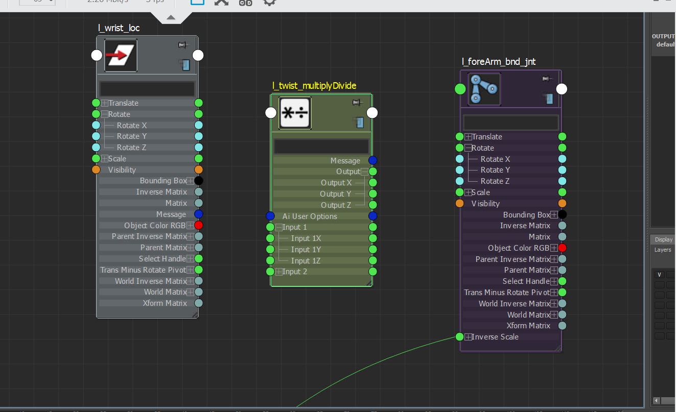
Using the Node Editor
- select locator and the Forearm joint and load into the Node Editor. Do not need the Shape or Elbow nodes, only the transform and the object that is being controlled.
- create a multiplyDivide node and put between the locator and forearm nodes, rename it l or r-twist_
- from the drop down options in the nodes select the Locator’s Rotate X Output and connect to the multiplyDivide’s Input1, Input1 X option.
- take the multiplyDivide’s output, Output X and connect to the input of the Forearm’s Rotate X. Only twisting in X.
- select the multiplyDivide node in the Attribute Editor and select the Divide operation. Then in Input 2’s first box enter 2, the bottom value.

What is happening with the multiplyDivide Node is it is using the value from Input 1 and is dividing by the value in Input 2. When Input 1 is = n then n divided by 2 = half of n. If I divide by 0.5 it will double the value. The node is outputting the result of the calculation which is what was happening with the expression earlier.
To finish the automated wrist rotation
- select the wrist locator and the wrist joint and in the node editor make a direct connection between the locator’s Rotate Output and the wrist joints Rotate Inputs. With a direct connection if something goes wrong it can be changed so long as the locator and the joint always line up.
The automating part of the forearm twisting functionality was applied to the bind skeleton rather than the control modules, then the control modules do not need to worry about it.
Check that it works, rotate the locator 90 deg and in the Channel Box the Forearm joint will be 45 deg. Rotating the wrist gives a half rotation on the Forearm.
Check that it works, rotate the locator 90 deg and in the Channel Box the Forearm joint will be 45 deg. Rotating the wrist gives a half rotation on the Forearm.
Now there is the issue of the Controller (the locator) not following the skeleton. Need to look at what is being used, what is being controlled, what it is affecting and what can be done to solve the problem. Will not use a parent because it needs to be kept separate form the hierarchy, translate is not being used for the wrist rotation, it can be used to have the controller follow the skeleton. A direct connection will not work because translates on joints cannot be frozen. A constraint uses the pivot points in local space, the direct connection uses the numbers.
- select the joint then the controller and use a Parent Constraint.
BIND SETTINGS

Select the root joint and the Proxy Geo Layer
- Skin
- Smooth Bind Options: Joint Hierarchy, Geodesic Voxel, Weight Blended, Post, Select Allow multiple Bind Poses, Max Influence 3, Maintain Max Influences OFF, Remove Unused OFF, Colorize Skeleton OFF Include Hidden Selections on Creation OFF, Falloff at 0.2, Resolution 256, Validate Voxel State SELECTED. Only select one skin.
FK and IK ARM MODULES
The setting up of the two different sets of arm modules. Using three joints, there is no need to include the forearm joint as this has been set up for the wrist twist with the bind skeleton using the wrist locator. The wrist twist is being driven by the wrist locator which is driving the forearm joint. If a rig was being made where the wrist might need to be changed than this would need to be set up differently, consider an independent wrist system though we are not doing that for this rig.
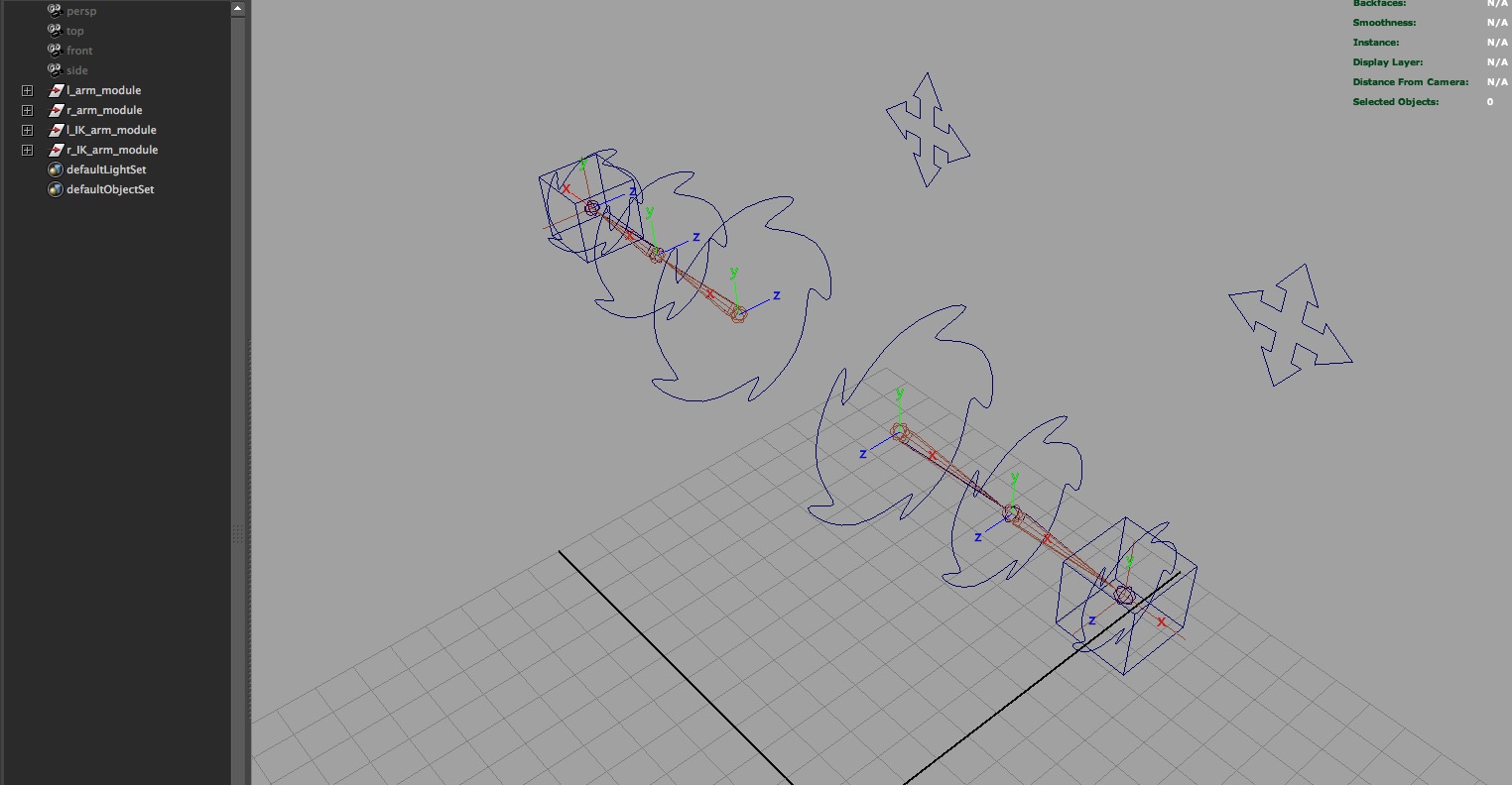
The locators are set were the joints are for the bind skeleton for the FK and IK arm modules to match and use a FK/IK switch between them. Joints have translate information on them and cannot be zeroed out.
- Skeleton > Joint Tool > default settings
- V snap joints to the locators creating three joints and two systems, one for the each the right and left arms.
- Check the orientations of the joints by selecting the top node and right click and select hierarchy to select the joint chain. Then Display > Transform Display > Local Rotation Axis and do for both sides.
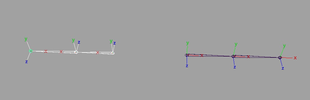
The left side is ok as it matches world space, the right side is working differently because the end joint is not matching the other orientations, X is facing the opposite direction. The end joint is at world space and needs to be oriented up the chain to match the other joints in the hierarchy, relative to its parent, the child needs to point to its parent not the environment or world space.

- Select the end joint on the right hand side, can use the right hand rule which is open to error when setting in different systems in how the rotations may be calculated. It maybe +180 in one and -180 in another and they are actually 360 deg apart, or have Maya do it for me. Go to Skeleton > Orient Joint Options > rest > Orient Joint to World, its world.
- Check the orientation of the bind skeleton and make sure they match.
- Rename the joints to l_shoulder_FK_jnt, do for the elbow and wrist and on both sides, r_shoulder_FK_jnt.
- Put the locators in a Layer, would normally delete, going to use for the IK module.
Setting up the control curves for the FK arms, the rotate, translate and pole vector controllers.
- V snap the first rotate controller and rotate to line up. Duplicate for the other joints and adjust the size so it can be seen outside the model and selected by the animator.
- Name, Freeze Transformations, Delete History. l_shoulder_FK_ctrl, do for the others and both sides.
How are the controllers going to be set up, as a mirror or parent hierarchy with the joints? Need to consider how it will work when the rig is finished and integrated. What do I want the joints to be doing? The joints that the curves control will be driving the bind joint and how this is set up will affect how the modules go together. Keep it independent, do not want something like the controller telling the joint to rotate and this joint is telling the bind joint to rotate, doing it twice. Seting up a system where there is a switch between one set of controls and another set of controls and keep them independent – a standard rotational hierarchy or mirror hierarchy. The controls are separate from the joints, in separate hierarchies, independent of each other.
- First set up the buffer groups or a null group. Control G with nothing selected and V snap to the first shoulder curve, freeze and move the pivot point.
- Name the buffer l_shoulder_buffer.
- A Parent Constraint is not necessary on the left side because the orientations match. When doing the right side then the orientations will need to match.
- Put the shoulder curve into the buffer, which is already oriented correctly.
- Repeat for the other controllers, group the elbow controller to itself, move the pivot point to the elbow, rename, freeze. Again repeating for the wrist. Shifting the pivot points incase something need to be done later and it is know where the pivot point is.
- There are three controllers in three buffer groups on the left side with the joints in their parent hierarchy and want to do the same for the controllers. The buffer is on the top of the hierarchy such as the wrist buffer into or parented to the elbow controller, the elbow buffer parented to the shoulder controller. The buffer groups do not move, do not appear on the interface, they are not animated, they parent objects to hold values. The controllers are what is changing. Do the buffers on the left so it is consistent, looks and works the same as the right.
- Connect all the joints up by selecting the control then the joint > Constrain > Orient Constrain options with maintain offset off. Do for all the controllers on the left. Select the control, the joint, G.
- Point Constraint for translate, select the shoulder joint then the shoulder controller > Constrain > Point Constrain with maintain offset off. If the joint moves everything will follow. A constrain to hold it all together, not a parent constraint as it has rotate and translate with an independent pivot. Already have an orient constraint on the joint from the controller, the curve is telling the joint to rotate and then there is a joint telling the curve to rotate ending up with a cyclic error with both controlling each other.
- Create a Left Arm Module Group by selecting the l_shoulder_FK_jnt and the l_shoulder_buffer_group.
SAVE
For the Right Hand Side do the same except for the buffer groups. It is important because the orientations do not match. The left worked because they are the same direction as world space.
- – Deselect everything and create a Null Group. Will build the group hierarchy first then put the curves into the correct groups then there is no need to reorient all of them, they will automatically have the offsets.
- Rename r_shoulder_buffer, move the pivot point to the shoulder
- Duplicate and rename elbow and move the pivot point to the elbow joint and do the same for the wrist.
- Parent the buffer groups, the wrist to the elbow, elbow to the shoulder.
- Orient the buffers
- Select the shoulder joint and the shoulder buffer, Constrain > Orient Constrain with Maintain offset off. There will be a 180 deg offset on the shoulder and will not be there for the elbow and wrist because of the hierarchy, not need to constrain the rest of the hierarchy as the hierarchy has done it with the child oriented to the parent.
- Delete the Orient Constraint, only used to orient the buffer.
- Put the shoulder into the shoulder buffer, elbow into the elbow buffer and wrist into the wrist buffer getting the control curves into the hierarchy.
- Make sure the controllers have the right names, freeze and delete history. Check the controllers can be zeroed out. The top buffer group will have the 180 deg offset.
Fix up the hierarchy to match the left arm.

- Each buffer goes into the controller of the one above it and can see this in the outliner. The shoulder buffer has the shoulder controller as its child, then the shoulder controller has the elbow buffer as its child, then the elbow buffer has the elbow controller, the elbow controller has the wrist buffer as its child with the wrist buffer as the parent of the wrist controller. The controller needs to affect its buffer as the buffer is there to hold the offsets values, with the buffer being the child of the controller with is up in the hierarchy.
- Check here because they have not been connected to the joints, make sure it works and can be zeroed out.
- Connect the joints up with an Orient Constraint. Select the controller then the joint > Orient Constrain with Maintain Offset Off for the shoulder, elbow and wrist.
- Finally a Point Constraint from the joint to the shoulder controller so everything follows.
Check and make sure it all works, can zero it off, then group together and name R_FK_arm_module
Make a layer and call it FK_arm_module_layer and SAVE
SETTING UP THE IK ARM MODULE
- Bring back the locators, turn on the locator layer and make a new set of joints.
- V snap to locators, rename l_shoulder_IK_ jnt. Do for each joint and both sides.
- Check the orientation, the same as we did for FK. Reorient the right wrist joint to Orient Joint to World so it follows the parent and check orientations with the FK module.
- Set the preferred angle by selecting the elbow and rotate in one direction, the direction it is going to move.
- Hide the locators
- V snap the controllers into place on the wrist, duplicate and V snap to the other wrist and rename them l/r_IK_translate_ctrl. Freeze Transforms, delete history and make sure it can be zeroed off.
- Pole Vector Controls in Place, V snap to the elbow, duplicate for the other elbow then move behind where the object will move to. Freeze, rename, l/f_IK_poleVector_ctrl.
IK is translate and for this there is no need to be concerned about offsets, does not need world space. Translate has no orientation issues, it is a point in space, no rotate orders as there is nothing going on in-between.
Do need to rotate the wrist and for this IK rig, either another controller that rotates the wrist with the IK system or use this controller to rotate the wrist as the IK stops at the wrist. For this rig there will be a buffer for the controller to rotate the wrist as the orientation of the controller and wrist needs to be the same with no offset values. Only need to do on one end, the wrist controller as it is the only one with rotation. There are two controllers that can be used to rotate the wrist with buffer groups to take the offsets. Do not need to do for the left as its orientation is in the right direction, do both so they look the same.
- Create a buffer for the right wrist controller and rename r_IK_buffer.
- Select the joint and the buffer and use a Parent Constraint, Maintain Offset off. Instead of moving the pivot it has been done with the orient with the Parent Constraint.
- Do the same on both sides, even though the left does not need to be oriented need the same system on both sides. Make a group, centre the pivot and rename.
ADDING THE IK
- Skeleton > IK Handle tool options, will do the same for both arms. Choose Rotation-Plain Solver and select the joints on either end of the hierarchy. The direction does not matter, it knows the hierarchy’s direction and will always go the right way. Rename l/r_IK_handle
Now to hook up the controls, the IK Handle is constrained to the Pole Vector and the IK Controller
- Select the Pole Vector Control then the IK Handle > Constrain > Pole Vector for both arms.
- Attach the IK Handle to the controls, Select the Controller then the IK Handle > Constrain > Point.
To set up the rotation, the IK has no rotational influence.
- Select the Controller then the wrist > Constrain > Orient with Maintain Offset off. To check the rotations work on the wrist when rotation the controller the values will change on the joint. To see this select the joint and look in the Channel Box.
SAVE
Group into a r_IK_arm_module and a l_IK_arm_module
SAVE
Need to tidy up before bringing into the bind skeleton file and start putting it all together.
Do not want any left overs such as locators, materials, nodes and history. Can always redo in the other file. Named correctly, organised so everything can be found easily and get rid of anything that does not need to be in the scene.
- Delete the geo, tempGrop and tempGeo and display layers, they can be set up again later and turn off the rotation order displays on the joints. Make sure the Pole Vector Controllers are out of the tempGroup.
- Layers, delete all of them.
- Hyper shade > edit > delete unused nodes. Any node that is not plugged in.
- Outliner, nothing there we do not want.
Save as a new name with clean or import ready as part of the name
Open the scene with the bind and wrist twist that are ready and set up.
Do not want to be binding when these modules are attached, there maybe some tiny values and even when everything is straight the tiny value somewhere can cause some issues with the bind and by the end of the fingers things may not line up properly. Sort out the bind rig first and make sure that is all working properly. The modules are build based on that rig, the locators line up.
IMPORT THE FILE
Import the file, turn off name spaces, tick group and the file will come in as a group to help with any naming conflicts. Tick remove duplicate shading network. Namespace options to classing nodes and this string as _a.

INTEGRATING THE FK and IK with the BIND SKELETON
The joints rotate, so hook up the rotations of the joints, the control joints to the rotation of the bind joints. Not using a direct connection as there is more than one control system and they need to work at the same time and also where the values can be changed so I can tell the system which one to follow. Will be using constraints. Could use the multiplyDivide node but this will not give me one or the other, it would do both at the same time.
CONNECTING the FK MODULE
There was a problem with the wrist twist and hand flipping later on in this tutorial when connecting the FK and IK modules. Direct connections and constraints do not play well together even though there appears to be no reason why not. An extra node has been created, a unit conversion and with the direct connection as soon as other things get involved it needs to get a value from somewhere and it starts pulling the value from the hierarchy, especially on the right side, dragging the offset from hierarchy instead of inheriting it. There starts to be issues with the constraints because of the way constraints and direct connections use their information, it is different. The direct connection needs to be deleted and rebuild with a constraint so the direct connections and constraints are not being used together. Constraints are always independent, they do not get involved in the hierarchy. Delete the direct connection before connecting the FK and IK modules because once everything is connected deleting the direct connection will not work. The connection has already been created, it stays in the background and continues to create problems.
MAKE SURE THE DIRECT CONNECTION THAT WAS SET UP ON THE BIND SKELETON BETWEEN THE WRIST LOCATOR AND THE WRIST JOINT’S ROTATIONS HAS BEEN BROKEN BEFORE CONNECTING THE FK AND IK MODULES
- this was created when setting up the bind skeleton and needs to be deleted: select the wrist locator and the wrist joint and in the node editor make a direct connection between the locator’s Rotate Output and the wrist joints Rotate Inputs
- now delete this connection between the rotate to rotate of the wrist locator and the wrist joint in the node editor
- Getting rid of the yellow value in the channel box. The connection with the multiplyDivide node is still there. Once it has been removed it needs to be added back in with an orientConstraint.
- select the locator then the wrist > Orient Constraint and maintainOffset OFF.
- Turn on the FK layer and do not need to see the controllers so put them in a layer and turn off.
Remember about the wrist twist, the locator is twisting the wrist, its rotations which are controlling the forearm. To control the wrist twist there needs to be a connection to what is rotating the wrist, it is not the joint. The joint is being influenced by the locator. Need to attach the control system to the locator on the wrist.
- Select the left wrist FK joint and then the left wrist locator on the bind joint > constrain > orient. If something flips or moves then something was oriented incorrectly.
- There rest are joint to joint orient constraint and do the same on the other side.
- turn on the controls
The bind skeleton wrist already has something controlling it, the locator. When connecting the FK controls to it select the locator on the Bind Skeleton for the wrist, not the joint. Using the FK control system to drive the Bind joints system.
Check as you go, test at each stage, the rotate values are at zero, the controls work, check the hierarchy so that the buffers have the offsets, the controllers can be zeroed off, rotation set to gimbal, the wrist twist is still working.

The FK is now working on the bind, there is a problem, the wrist is turning the hand. The rotation is travelling down the hierarchy from the shoulder to the locator. This is meant to be happening through the hierarchy, it is a mirror hierarchy. It is getting the rotate value from the shoulder. There is a yellow value in the channel box for the bind wrist joint, a direct connection and direct connections and constraints do not mix well. This needed to be broken before connecting the FK and IK modules as described at the beginning of this section and following here.
- break the direct connection between the rotate to rotate of the wrist locator and the wrist joint in the node editor. Get rid of the yellow value in the channel box. The connection with the multiplyDivide node is still there. Once it has been removed it needs to be added back in with an orientConstraint.
- select the locator then the wrist > Orient Constraint and maintainOffset OFF.

The constraint is doing the same thing with the locator controlling the joint. Using a constraint instead of a direct connection. The FK and IK arm modules are being integrated using orient constraints when they are hooked up and direct connections cannot be blended.
The FK control system is only controlling the rotation, the joint is being controlled with the rotate of the controller, translate is not being affected which means it is not travelling with the bind skeleton.
Select the clavicle bind joint then the arm FK module and constrainParent, the module does not have the orientation values to match the clavicle bind joint. By taking the joints and the control system out of the group it makes a null group. This can then be oriented to the clavicle joint and it will gain all the orientation and translate values of the clavicle joint. Because the joints and control hierarchies have been taken out they are not directly affected as they would have been had they been left in the group. The group matches the orientation of the clavicle joint. Put the two mirrored hierarchies back in the group and as it is already constrained they go in with the offset already in place. A buffer group has been created. The group is receiving all the orient and translate offsets and not transferring anywhere past the shoulder buffer.
- take both out of the group and then there is at the module null group so they do not inherit the offsets
- put the pivot point on the clavicle
- parent constrain the armFK module to the clavicle to reorient it to the clavicle joint Select the clavicle joint then the armFKmodule Null Group
- put back the shoulder and buffer hierarchy
- do for both sides

CONNECTING the IK MODULE
Make sure the direct connection has been broken, as described at the beginning of the section, before connecting the FK module. The IK shoulder joint hierarchy needs to be in the buffer group with the controller.
IK joints are rotated based on the position of a goal called an end effector. To connect the IK module to the Bind Skeleton, start the same as done for the FK by
- select the joint, left_shoulderIK_joint then the left_ShoulderBind_joint and orient constraint
- do the same for the elbow and wrist locator
- on both sides
For the bind joint in the channel box there will be two inputs, FK joint and IK joint.
There is the same problem as the FK module, it is not following the bind skeleton. The difference between the two modules is that, the IK is translated based while FK is rotations. The IK has nothing controlling the rotate, no rotate inputs and there is no mirror hierarchy from the arm control module so it cannot be connected the same way. The IK handle is involved and it is not needed to follow the skeleton, needs to stay behind. Cannot do the same thing with the IK, it is a reverse system.
- point constrain the shoulders so they follow, the IK shoulder to the bind shoulder.
There was a problem in our class with this, some people were getting unwanted values with the rotations. Make sure there are no values on the joints either FK or IK rig, rotate values or offsets values on the joints. If so there is a problem. Ignore translate as joints always work in world space. Couple of zeros is ok only on IK, not so much on FK.
Again this is a problem caused when the direct connection that was not deleted before starting to add the FK and IK modules. When the direct connection is deleted from the bind skeleton first this problem does not occur and the work around below is not required. How to do this is explained at the beginning of setting up the section for connecting the FK module.

Needed to undo because when more than one orient has been mixed together they do not make another constraint node, it adds the weight to get the two inputs on the one node. Other than undoing the only other way is to delete the constraint node and reconnect both the FK and the IK. Check the bind joints and the locator that they have FK inputs and no IK inputs.
Will do the same thing that was done on the FK system, use a buffer on the clavicle and retain the custom orientation on the clavicle. Do not have this problem on the left because we do not have the 180 deg offsets.
- pull everything out of the IK arm module group, the IK control buffer and the IK handle starting with an empty IK group
- parent constrain the IK module null group to the clavicle joint. The null group will gain all the offsets from the clavicle, inherit the offsets
- put the pv control and shoulder joint back into the arm module group, leaving out the IK handle and the IK handle control, make sure the default values of the pv controller have been reset to zero
- connect the rotate values of the IK joints to the bind joints, shoulder to shoulder, elbow to elbow and wrist to wrist locator
The bind skeleton moves the IK follows from the shoulder and the rest of the IK system stays behind.

SET DRIVEN KEYS
Creating a switch that the animator can use to move between the FK and IK arm modules. There are three joints, the shoulder, elbow and wrist locator and two sets of controls the IK and the FK telling the bind joints what to do. The IK is driving the bind and the FK is driving the bind and the SDK is a switch between which system is driving the arms joints of the bind skeleton.
The switch will move character’s arm from Forward Kinematics, which is Rotations, to Inverse Kinematics, which is Position, by changing the added attribute in the channel box from 0 to 1.
The IK handle bends with translate even though it is still rotating the joints, it is doing it in the background. These joints are telling the bind skeleton to match those rotations and there is the the switch saying which system to follow.
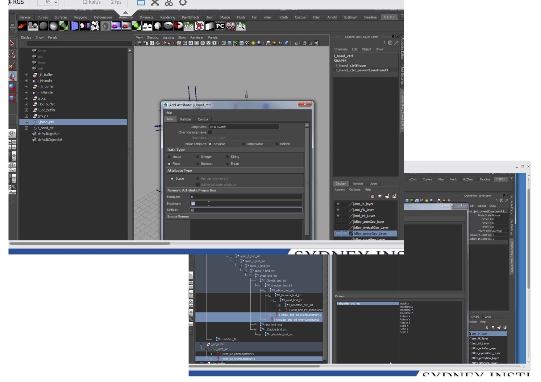
- create a controller to use for the switch for both the left and right sides and add the switch attribute
- in the channel box > edit > add attribute. Call it IK_FK_switch, float, min = 0 and max = 10 and default = 0.
- IK = 0 and FK = 1
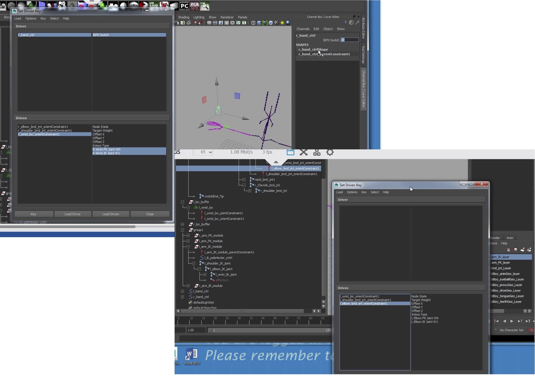
- animate > set driven key > set
- the driver is the left/right switch controller
- the driven are the orient constrains that have been set up between the modules
left/right_wrist_locator_orientConstraint
left/right_shoulder_bind_joint_orientConstraint
left/right_elbow_bind_joint_orientConstraint
In the Channel Box set the IK_FK Switch depending on which module is being connected for each of the driven attributes. When at zero follow that one and at at one follow the other one.
– hand controller channel box is set to 0 for IK.
– select the r_elbow_orientConstraint want FK off and IK on = 0 and 1
– make sure to select the two values for the driven and KEY
Repeat for all the constraints and both sides.
Two check turn on the two systems and when switching in the channel box it will follow one and not the other, using the IK_FK switch to blend between them. If it is at zero it is only following the IK, if it is set to one it is only following the FK
Remember to make sure the animation curves are set to linear. It is an animation between keyframes and the blending will not work smoothly otherwise, it is up to the animator to decide how the blending will be animated.
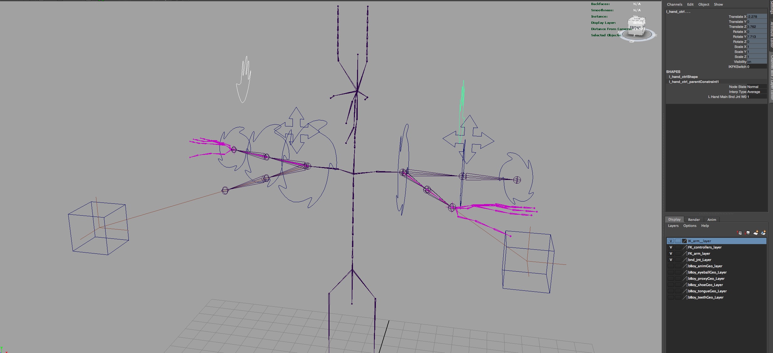
Books:
Cabrera, Cheryl. An Essential Introduction to Maya Character Rigging with Dvd. Boston, MA: Elsevier, 2008.
Derakhshani, Dariush. Introducing Autodesk Maya 2013. 9th ed. Indianapolis, Ind: John Wiley & Sons, 2012.
O’Hailey, Tina. Rig It Right!: Maya Animation Rigging Concepts. New York: Focal Press, Taylor & Francis Group, 2013.
Palamar, Todd. Mastering Autodesk Maya 2014: Autodesk Official Press. 1st ed. Indianapolis, IN: John Wiley & Sons, 2013.
Ritchie, Kiaran, Kiaran Ritchie, and CG Toolkit (Firm). The Art of Rigging. Vol. 1, A Definitive Guide to Character Technical Direction with Alias Maya. [United States]: CG Toolkit, 2005.
Rodriguez, David. Animation Methods: Rigging Made Easy : Rig Your First 3D Character in Maya. Lexington, KY: CreateSpace, 2013.
Web:
Michael Comet, a modeling/rigging artistic/technical director at Pixar Animation Studios and the original creator of Maya Muscle, has bottled these tools’ functionalities to take them a step further. He offers an easy-to-use script called cometRename that can handle all of your renaming needs.
Author: Scott Ziong
http://scottxiong.com/the-importance-of-joint-orientation/
Introduction to rigging in Maya – The shoulder and the arms, Author: Jahirul Amin
http://www.3dtotal.com/index_tutorial_detailed.php?id=1846#.VVhSNM7Jf8s
Maya Rigging – Rigging a biped character for animation Author: Steven Murdoch
People:
Last but not least, Michael Allison’s classes, all his knowledge that was shared and that has made this what it is.
What is rotate order, why is it important
and how can it help or hinder the animator?
Rotate order is how Maya calculates the rotation of three axis in 3D space, XYZ, in order to come up with the final position or end point.
The rotation is worked out based on rules using either a Quaternion or Euler Rotation method. In Maya Euler Angles are favoured using a combination of the three angles to calculate the rotations in three dimensions, based on the rotation of the three axis.
The first rotation is a single vector or straight line ‘Real Line’ calculating the distance from the start to the end point. The second point or dimension has two vectors perpendicular to a common axis point creating a plane to calculate the point in space, ‘Cartesian Plane’. The third dimension or ‘Coordinate Space’ is using three cartesian planes, three numbers to calculate a position within a volume in all three dimensions.

Wikipedia, Euclidean Space: http://en.wikipedia.org/wiki/Euclidean_space and http://traditio-ru.org/images/6/63/Euclidean_space%2B.jpg
Every point in three-dimensional Euclidean space is determined by three coordinates.
The rotations in XY and Z rotate are on their own axes in a hierarchical sequence with one following the other. When the first axis is rotated the other two do not move, when the second axis in the hierarchy is rotated the first one rotates with it and the third does not follow. The third axis is rotated and both the others rotate, all three axes are rotated.
Each of these rotations are defined by their own axis and because of the hierarchical nature of the calculations, the order of the calculation, the final position of the object being rotated changes in Euclidean Space.
The default rotation order is XYZ, where Z is the parent, Y is the first child and X is the second child. Y will move the X and Z moves all of them, with X being the twisting axis, Z rotating up and down and Y side-to-side. This is the hierarchical way they relate to each other.
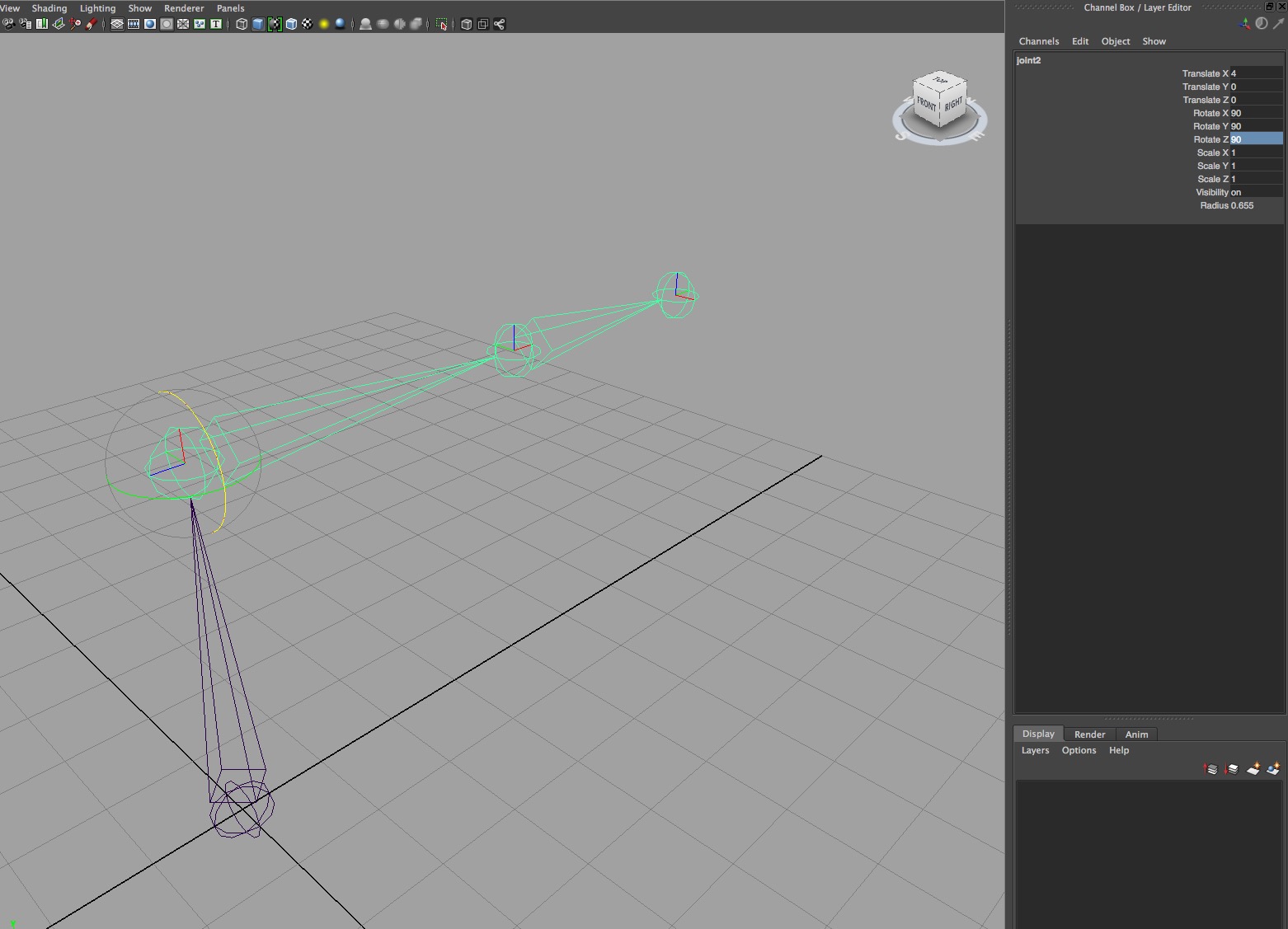
When I use the default rotate order, XYZ, in the Attribute Editor and move the joint 90 deg in X first, then Y then Z in the Channel Box, the above shot is the result.
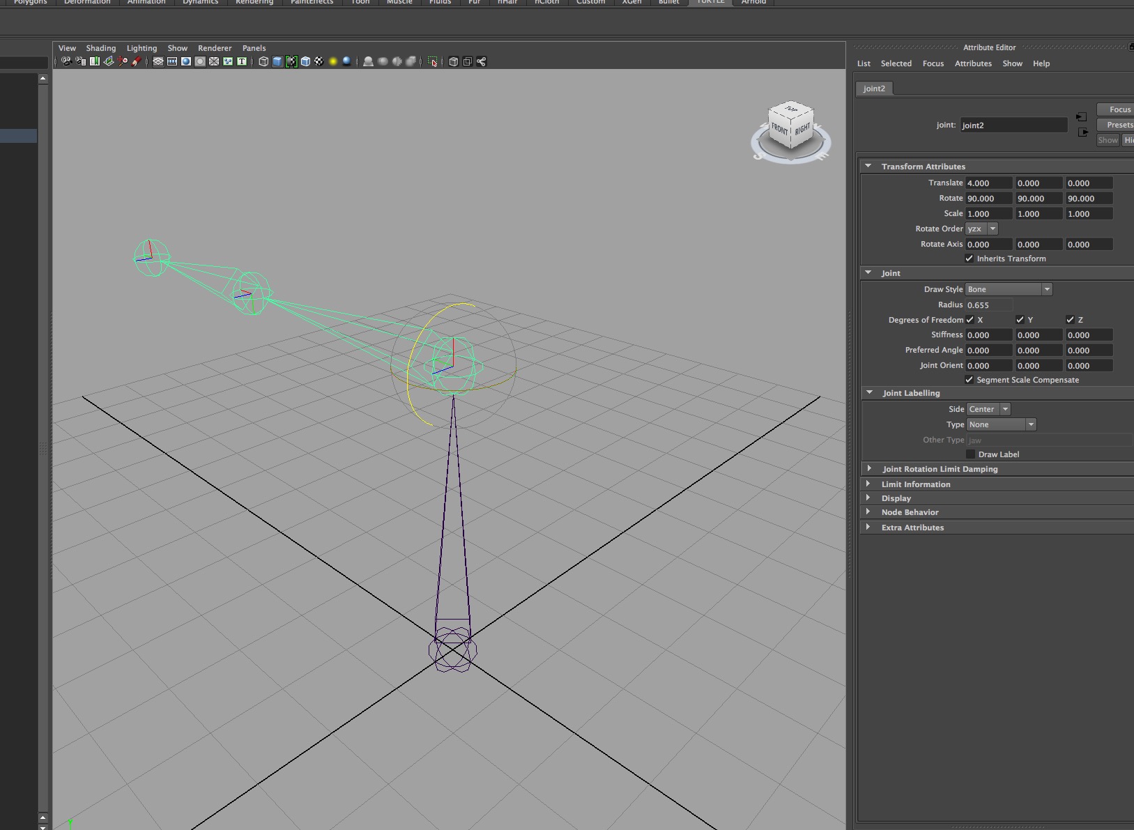
When I change the rotate order, the order of the hierarchy, to YZX for example and enter the same values, in the same order, in the Channel Box as for the previous example, the resulting differ. The order or the way the calculation has been done has changed the final position. Maya is looking at the end result based on the rules for the calculation, Eular Rotation.
Another issue to consider with how rotation is calculated is Gimbal Lock, the loss of one degree of freedom due to parallel orientation. It is when two rotation axis are doing the same thing, the axes are overlapping and preventing the joint from rotating in three dimensions, losing an axis of rotation. This is important because the rotation order affects how the object is going to move or behave giving different results.

O’Hailey, Tina. Rig It Right!: Maya Animation Rigging Concepts. New York: Focal Press, Taylor & Francis Group, 2013. page224
I have used this shot from Rig It Right because I think it show this very clearly.
This middle axis is rotating the child, the first axis, but not its own parent (last axis) and always causes gimbal lock. The middle axis is lining up its child with its parent. The first axis rotates freely not affecting the other two and the last axis, the parent of the other two, rotates both axis so they do not ever line up. When the rotate order is changed the parent, child hierarchy changes and the order of calculation has changed.
There can also be flipping issues, Maya does not know the difference between 0 and 360 deg. It is how the curves are calculated, not how many rotations. Maya is calculating the interpolation between two numbers deferring to the smallest value as opposed to the shortest path.
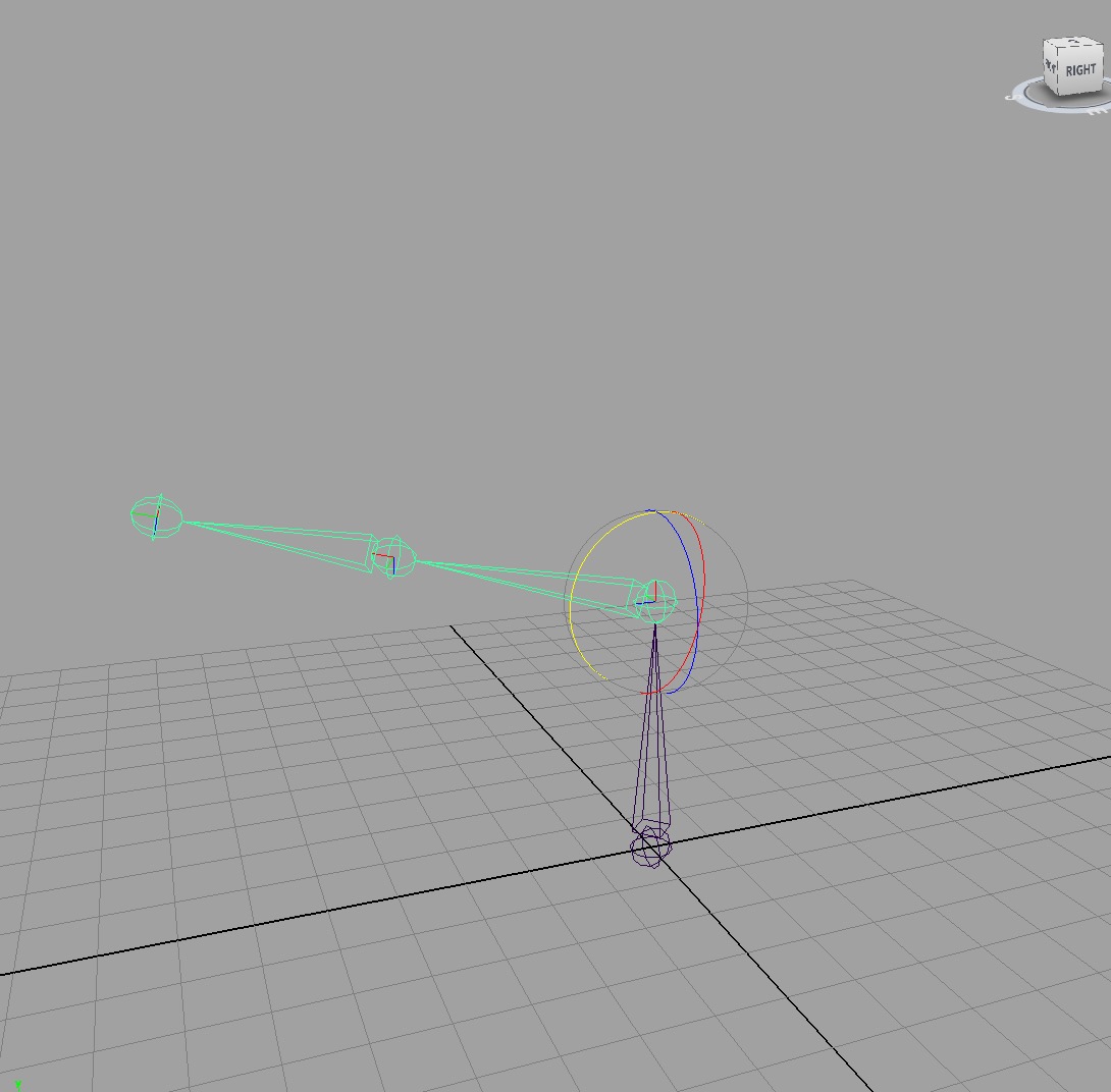
When two axis are overlapping Maya does not know what axis to rotate, the general rule is to put the middle axis where there is little movement. What movement is important, the twisting, the side to side or the up and down?
The lease important movement is most likely the best place for the middle value which causes Gimbal Lock with the most important rotation last as it is the parent of the other two.
The rotate order is important for the animator with the best rotation order for a particular joint or control varying depending on the range of movement and action.
Selecting a workable rotate order allows for the rotation of the joints to move the character or object with the least amount of compromise in the rotations and causing minimal interference when gimbal lock occurs. Changing rotate order does not eliminate gimbal lock, it moves it to a different position.

Gimbal Lock Video: Silke, Andrew. (2009) Eular (Gimbal Lock) Explained, The Gurerilla CG Project, https://www.youtube.com/watch?v=zc8b2Jo7mno
Setting a suitable rotate order stops strange rotation pops in the graph editors curves, the animator needs predictable results. It is difficult to animate the node when the axis cross making the animation curves difficult to manage.
Having gimbal lock in a place where the character or object is lease likely to need extremes in rotation, still giving the control needed for the required actions and reducing the possibilities for getting gimbal lock and flipping is important for the animator. Having the object move unexpectedly affects the stability of the character.
Reference:
Rig it Right! Maya Animation Rigging Concepts – Tina O’Hailey
– videos
Euler (gimbal lock) Explained
Animation Methods Scripts Link
Cabrera, Cheryl. An Essential Introduction to Maya Character Rigging with Dvd. Boston, MA: Elsevier, 2008.
O’Hailey, Tina. Rig It Right!: Maya Animation Rigging Concepts. New York: Focal Press, Taylor & Francis Group, 2013.
Palamar, Todd. Mastering Autodesk Maya 2014: Autodesk Official Press. 1st ed. Indianapolis, IN: John Wiley & Sons, 2013.
Ritchie, Kiaran, Kiaran Ritchie, and CG Toolkit (Firm). The Art of Rigging. Vol. 1, A Definitive Guide to Character Technical Direction with Alias Maya. [United States]: CG Toolkit, 2005.
Rodriguez, David. Animation Methods: Rigging Made Easy : Rig Your First 3D Character in Maya. Lexington, KY: CreateSpace, 2013.
Other References:
Welcome to Michael Comet’s Homepage
and Maya Downloads
TUTORIALS
Creating a Character Rig – Part 10: Basic IK, FK, and result leg joints
Creating a Character Rig – Part 12: Leg FK control
Demonstration 18: Rigging Chubby

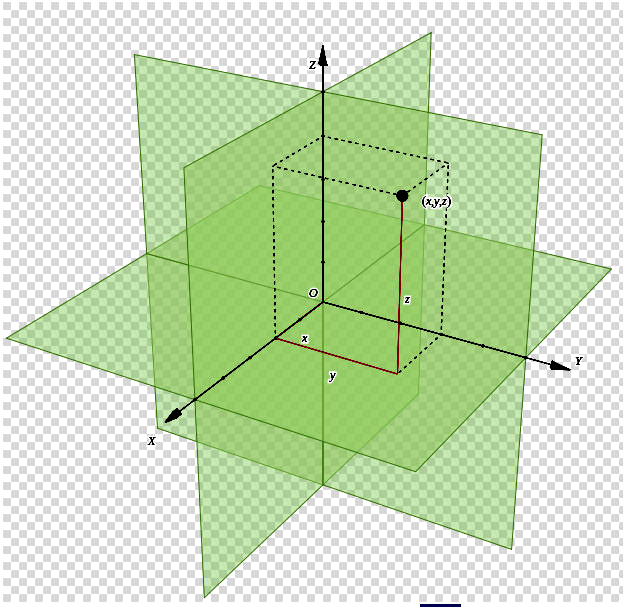