Decode Programming with our Beginner’s Guide
w3schools.com: The language for building web pages
Women Who Code: Sydney and Meetup
Sydney Python User Group (SyPy) Monthly Meetup
EAT 3D Autodesk Maya Scripting – An introduction and Applications Luiz Kruel
LESTER BANKS: LEARN ARTIST FRIENDLY PYTHON FOR MAYA FROM DHRUV GOVIL
Quality Coding, Inc. YouTube
STACK SOCIAL PythonProgramming Bootcamp
MICHAEL COMET – MEL Script Suite
This section contains all of my Maya MEL Scripts AND Maya Plug-ins that I have released. All of these items are supplied as is. You alone are soley responsible for any issues, damages or effects of the software, I make no warranties either implicit or implied as to the useablity, safety, or quality of the software. Use at your own risk.
This link is a special inclusion requested by Girl Scout, Katie Miller who contacted me after finding some of the information on this web page helpful for her Junior Digital Game Design Badge. The VR Coding Design web site is part of the resources they found and used by her Girl Scout troop’s work towards their badge. It covers the most popular programming languages for VR and everything you need to get started for developing virtual reality games. Virtual Reality has also been incorporated into Katie’s school curriculum. I was a Guild Guide myself in my youth, not admitting my age here and thought this was wonderful and very excited to include as part of these resources. I went looking for information and found this: Girl Scouts at Home: Juniors – Digital Game Design Badge
Coding with Style (in Python)
The core point of Scripting for Artists is not skill but a round up solution of multiple layers. The mixture of skill, mindset and branding creates opportunities and a fulfilling path of working your way, under your conditions and understanding.
Python For Beginners
Welcome! Are you completely new to programming? If not then we presume you will be looking for information about why and how to get started with Python. Fortunately an experienced programmer in any programming language (whatever it may be) can pick up Python very quickly. It’s also easy for beginners to use and learn, so jump in! PYGAME Do all the boring tutorials like creating calculations and “hello world”, understand what functions, loops, arrays and conditional statements are, what passing by reference vs passing by value means. Then there are all the python high-level specific things like maps and dictionaries and you need to understand all of this before you can start mixing python with maya.
Introduction to Python Scripting in Maya – Available at https://gumroad.com/l/oUpTB
This tutorial series introduces basic python functionality in the Maya environment. For artists and designers accustomed to thinking visually, Maya’s 3D environment is a great space to learn to script. Each topic is described in short, concise chapters, without a lot of extra information. Larger projects sprinkled in to demonstrate tools discussed in previous chapters. This series is intended to introduce the uninitiated to how awesome scripting can be, and is intentionally narrow in its scope. There are many excellent resources available for those interested in a deeper look.
Lecture 0: Introduction – Computing 1 – Richard Buckland UNSW
Introduction to Python Scripting in Maya – Available at gumroad.com/isaacoster
A top-down approach to programming helps to visualise the overall structure. A Structured Programming is a collection of methods for logical organisation. Broken down into parts, or modules with each performing a task. Starting with as complete as possible a description of what the program is to do. Look at the modules, what each module will represent, starting with the major modules then break each of these into smaller modules. The bottom-up approach ensures that the working parts really work and a combination of these to adapt and organise the modules when designing a program. When writing programs:
- need to be able to look a the source code and see how the program works, what each part does and how the parts interact
- the programmes the least amount of the computer’s resources
- the source code is concise
There are two fundamental parts:
- algorithm which need something to manipulate, data, a sequence of instructions which solves a single problem
- data, files, arrays, look-up tables, queues, stacks, lists, trees
THE ILLUSTRATED COMPUTER DICTIONARY and HANDBOOK Cowan, L., 1996, Enrich, San Jose. Even though this is an older book the following explanations of concepts and processes is a selection that was helpful in understand some of these regularly used words. The book includes lots of great drawings to further explain it all. There has been some of my own research included here. A program is a sequence of instructions, written in code, which direct the computer through the performance of a job in some sequence. Computers can be programmed to change that sequence depending on some condition. What the computer understands is something called its instruction set, the code for each instruction is very different. Computers code information into numbers, binary numbering.
- ARGUMENT Some commands require one or more arguments, which are numbers that tell the computer how to use that command. For example, the BASIC command PLOT tells the computer to draw a point on the screen, but it requires two arguments to locate where that point should be.
- ARRAY A section of a computer’s memory set aside to store certain information. A number of blocks with each one holding a unit of information. An array maybe two-dimensional in rows and columns, could have one row and maybe have more than two dimensions.
- ASSEMBLY LANGUAGE Instructions int eh instruction set are represented by words of trow or three letters, called mnemonic then an assembler will automatically convert his mnemonics into machine language so the microprocessor can understand it. The binary words of machine language and the mnemonic words of assembly language stand for one instruction each, each word of a high level language stand for a whole routine.
- ASSIGNMENT STATEMENT A statement which tells the computer to assign a value to a given variable. For example, the BASIC statement, LET A = 2, tells the computer that whenever it meets the letter A in the program, it should act as if it were the number 2.
- BASE Numbering system. Base two or binary, of two digits, zero and one with three written 11. The electrical signals in a computer are either high voltage (one) or no voltage (zero). Could be base eight 0-7, base ten 0 -9, base sixteen 0-9, A-F or hexadecimal.
- BINARY A base two system of two digits, one and zero. (on or off, open or closed) Each column has a value two times that of the one before it. The right most column stand for ones, the next for twos, the next for fours etc.
- BIT One digit in a binary number.
- BOOLEAN one stands for true, zero stands for false. A true or false statement. Boolean algebra is a set of rules that tells us what the answers to to problems are and can have different combinations of truth and falsehood.
- BUS A path for signals which are sent and received by components inside a computer. Address bus, data bus and control bus.
- BYTE The number of bits that are necessary to represent the code for one alphabetic character. Most commonly , a byte is eight bits long.
- CALL A kind of instruction. A call instruction tells a computer to execute a series of other instructions which are already in the computer’s memory, beginning at a location which the user specifies when he gives the call instruction. The programmer can give a label to a group of instructions in memory and from then on, can use one instruction (the CALL instruction) to put that group into action. Such a group of instructions is called a ROUTINE.
- CPU Central processor, executes instructions and manipulates numbers and controls the computer’s other operations.
- CLOSED LOOP A series of instructions which are executed over and over again because the last instruction tells the computer to go back and start the series over again. Usually this is caused by a mistake in the program. A closed loop can also be a job which the computer does without human interference, because the computer can tell when conditions change and change its own actions accordingly. For example, if a computer is attached to a thermostat turns a heater on and off depending on the temperature, we say that the computer, the thermostat and the heater form a closed loop.
- CODE Generally, any set of characters that stand of different characters. Every programming language is a code in which characters stand for different combinations of ones and zeros (machine language). Therefore, we refer to the written lines of a program as lines of code.
- COMMAND Loosely, the same thing as ‘instruction’. Can be an electronic impulse as distinct from a written instruction. Most instructions have several parts. For example an ADD instruction may tell a computer to add then tell it what numbers to add and where in the computer to put those numbers.
- COMMENT A note, written in English, which is part of a program and explains and clarifies what the program does. Special characters accompanying such notes tell the computer to ignore them.
- COMPILER A program that translates another program written in high level language into a machine language version which a computer can understand.
- COMPUTER LANGUAGE Any code which is used to write instructions that a computer will obey.
- CONDITIONAL BRANCH A program may tell a computer to do one of several things. Which one it does depends on some condition. For example, if a statement is true, do one thing, if it is false do something else, if its truth is unknown do a third thing.
- CONSTANT Is a symbol which always has the same value such as when the computer encounters the letter X, it must treat it as the number 18. The opposite is a variable.
- CONTROL STATEMENTS Decide which part of a program is going to control the next actions of the CPU. If……Then, has two instructions and a condition in between.
- DATA, Datum Computers need the information to be represented by numbers, binary numbers. Coding information into numbers using computer code for characters such as ASCll code. In ASCll, the numbers 0 to 9 are encoded as binary.
- DIGITAL Breaking things down into tiny parts which can be represented by numbers.
- DIRECTORY A list of files kept in mass storage, along with their contents.
- ELECTRONIC SIGNALS When data is transferred from on place to another, within a computer system, it is transferred in the form of electronic signals, patterns of electrons.
- ENCODING Is the process of converting data from one form to another. Computers use numbers to stand for all kinds of information.
- FLOATING POINT ARITHMETIC Arithmetic operations which can handle accurately numbers containing decimal points.
- FREQUENCY The number of times a signal repeats its impulses in a unit of time.
- FUNCTION Any single action that a computer can perform such as addition is a function, calculating the differential of an equation is a function
- HIGH-LEVEL LANGUAGE A computer language that is easier for people to understand and are slower than low-level languages which are easier for computers to understand.
- IDENTIFIER A word used to identify a memory location such as the name of a file in mass storage. When the computer is expecting a file name and it receives the identifier, it recognises that word as standing for a number. That number is the location of the start of the file on a disk. Identifiers also stand for memory locations of programs or parts of programs.
- IMAGE An exact copy of a section of memory that has been transferred to another section of memory or to a different location in mass storage.
- INDEX Often blocks of data are moved around in memory. Therefore, a datum (a piece of information, a fixed starting point of a scale or operation) will not always be at the same location, but it will always be at the same location relative to the beginning of the block. This distance from the beginning of a movable block of data is called the index.
- INITIALISE A DISK Records various signals on the disk which become markers then the computer can find a location by counting these markers.
- INITIALISE A VARIABLE A program stores a variable in a memory location. Variables are usually set to a starting value, often zero, when a program begins.
- INSTRUCTION A character or group of characters which represent, in code, an operation for the computer to perform and the memory locations and values involved in performing it.
- INSTRUCTION SET Every microprocessor is designed to perform certain operations and each of these operations can be repeated and combined into sequences to do complicated jobs. Together, these simple operations are called the instruction set,
- INTEGER The whole numbers and their opposites. Fractions and decimals are not integers.
- INTERPRETER A program which translates instructions in a high-level language into machine language.
- JOB CONTROL LANGUAGE A programming language used in programs which control the procedures needed to run a job on a large computer. These could include scheduling, allocating memory space, charging a job to a department.
- JUMP In programming, a jump is when the computer executes an instruction that does not follow the previous instruction sequentially.
- KEY WORD A word chichis used as an instruction or part of an instruction and such a word may not be used for any other purpose in programs written in the that language. Another meaning is a word for which a computer searches when retrieving information such as files in a data base.
- KILO A prefix which means on thousand. In computers memory is measured in powers of two, and two to the tenth is 1024. So a kilobyte of memory is not one thousand bytes, but 1024 bytes.
- LANGUAGE PROCESSORS The high level language (uses words), this source code needs to be changed into machine language, or object does of ones and zeros. One kind is a compiler which changes the entire source code into machine language on one pass resulting in an object code program that is ready to run. The other is an interpreter that changes the source code into machine language while the program is running, one statement at a time, so no object code program ever exists as such.
- LEAST SIGNIFICANT DIGIT In a number with more than one digit, the digit that stands for the smallest value. In number 1234, it is four as one stands for one thousand.
- LINE NUMBER Some programs are organised by lines with each line containing one or more instructions and the computer begins executing the program with the lowest-numbered line.
- LOGICAL OPERATION An operation in which a computer makes a decision, as distinct from one in which it performs arithmetic. If a computer does one of two things, depending whether a condition is true or false, that is a logical operation.
- LOOP In a program when something is done over and over again such as counting people going through a turnstile.
- MACHINE LANGUAGE or Object Code A program language in which all instructions are coded as binary numbers, so that any number or later is expressed as a combination of ones and zeros. Before a computer can run a program it must be translated into machine language, usually by a translator program such as an assembler or a compiler.
- MANTISSA With computers, it usually means that part of a number to the right of an including the decimal point.
- MATRIX A way or arranging things into pattern of horizontal rows and vertical columns. This kind of arrangement has a number of special uses, among which are converting data from one code to another and performing certain kinds of mathematical tasks.
- MEMORY ADDRESS A location, that is given a number, this memory address is used to locate data with in memory.
- MNEMONIC A coded instruction for the computer to add two numbers might be 10000110 in machine language, which is hard to remember, the same instruction in assembly language might be ADD, which is mnemonic.
- MOST SIGNIFICANT DIGIT The digit that stand for the largest value. In 1234, the one that stands for one thousand is the most significant.
- NIBBLE or NYBBLE Half a byte, usually four bits.
- OBJECT PROGRAM The machine language version of a program after it has been assembled or compiled
- OCTAL A base eight numbering system.
- OPERAND The object of an operation. For example, the operation code MOV n, 1 might mean move the number represented by n to the memory location represented by 1. Here, n and 1 are operands and MOV is the OPERATOR.
- OPERATION An elementary action that a computer can take, such as adding two numbers or moving a number from on location to another.
- OPERATION CODE A code symbol for an operator. As in example for Operand.
- OSCILLATOR Puts out regular electronic pulses, millions of pulses a second and everything inside the computer is synchronised.
- PARALLEL Working or traveling side by side, such as data being transmitted in parallel. Serial would have the data going out at different times.
- PARAMETER Some commands or parts of programs carry out actions which vary according to the value of some number or letter. These numbers are called parameters. For example, take a program selection from a block of text all the words that start with a given letter. The letter given to that program would be its parameter. The term is used interchangeably with the term argument.
- PEEK To display the contents of a single memory location.
- POKE To enter a value into a single memory location
- ROUTINE The programmer can give a label to a group of instructions in memory and from then on, can use one instruction (the CALL instruction) to put that group into action. Such a group of instructions is called a routine.
- SERIAL Working or traveling one after the other, at a different time. Parallel transmits data on different wire a the same time.
- SET To change the number held in a memory location, variable, flag or other value from zero to one.
- SOURCE CODE The code in which a program is originally written. The computer automatically translates source code into object code. Object code is machine language which the computer can run.
- SOURCE PROGRAM A program is originally written in a programming language. Then it is translated by the computer into machine language (ones and zeros that the computer can run). The program as written originally is the source program and the machine language version is the object program.
- STATEMENT A source program consists of statements, each statement consists of one mor instructions that tell the computer to perform various operations.
- STATEMENT NUMBER In some programming languages, including BASIC, each statement is given a statement number, with the lowest numbered being run first.
- STRING A group of characters which the computer treats as a single whole. For example, a word of text consists of several characters, the computer stores these characters as a word in consecutive memory locations. The word is a string of characters, which could also consist of numbers. Numbers in a string are treated as text and cannot be used in arithmetic calculations. A group of characters treated as a single unit and treated as a whole.
- STRING VALUE A string of numbers is treated as text and cannot be used in arithmetic calculations. However, a string of numbers can be converted into the same number for calculations and that number is called a string value. The string 1234 has the sting value of 1,234. A string consisting of numbers and letters has the sting value of the numbers before the first letter, 1234abc567 also has the string value 1,234.
- STING VARIABLE Some computer languages, notably BASIC, let you use a character to stand for a string. The instruction ST$=”this is a string” means that whenever the computer sees the symbol ST$ it acts as though it were the sting “this is a string”. A symbol like ST$ that stands for a string is called a string variable. Other examples VALUE$=”$4.95″.
- STRUCTURED PROGRAMMING The central ideas are that a program can be divisible into parts and sub-parts that can be executed as the result of only one other part or sub-part.
- SUBROUTINE A part of a computer program which performs a specific task and is repeated more than once in the course of a program.
- SYNTAX The rules for arranging the parts of a statement in any language.
- SYNTAX ERROR When the syntax is incorrect.
- SYSTEM COMMANDS Instructions that govern operations performed by a computer’s operating system.
- TASK A job can consist of tasks which can be run separately.
- TURTLE GRAPHICS The LOGO programming language can be used to program little figures known a turtles to move about a computer display, drawing geometric shapes as they go.
- UNCONDITIONAL BRANCH (TRANSFER) A program may have several parts, each of which makes the computer perform a different set of operations. When control of the computer is passed from one part of a program to another part, that is called a branch. When, at a certain point in the program a branch always occurs it is an unconditional branch as opposed to a conditional branch.
- VALID Acceptable to the computer. When a computer is running and is given a command that is not part of that language’s vocabulary, the command is not valid.
- VALUE Generally, the number that something represents at the moment. In logical operations, the value of a true statement is always one and the value of a false statement is always zero. The value of a variable may change, the value of a constant is always the same.
- VARIABLE A character of other symbol that stands for a number which may change in the course of a program. Everything to the left of the equal (=) sign is a variable. When the computer sees the letter A it means 5, somewhere else in the program it may change the value to any other number. The opposite is a constant, a symbol which always has the same value such as when the computer encounters the letter X, it must treat it as the number 18. Is one kind of memory address which has been reserved and given a label.
BOOKS
Unix Network Programming by Richard Stevens Hacking the art of exploitation BY JON ERICKSON
OTHER INTERESTING INFO
Use long names when writing your code Dragos Ionel
KHRONOS GROUP
 Notes from Live-drawing with Code and Immersive Virtual Measurement & Analytics lecture including HPC Visualisation demos at the Expended Perception and Interaction Centre (EPICentre) on 16 August 2017 at UNSW Art & Design. Khronos APIs: OpenCL OpenGL OpenGL ES WebGL WebCL COLLADA OpenVG OpenSL ES OpenMAX AL OpenMAX IL EGL StreamInput OpenVX OpenWF OpenKODE OpenML. MeetUp James Riordon Organiser, Sydney. Abstract: Everything starts with a pixel. Once you know how to display a dot, you can draw almost everything without any limitations. Things became simpler – you don’t need to know operation on bits to draw a ghost or a flower, or remember hexadecimal numbers to animate shapes. However, you still need to know a bit about hardware, its limitations to produce efficient code and creative real-time visuals. Ninjas can achieve almost impossible, even control Big Data of 64kb. Ninja Hack Art is alive in connecting dots of art and science, making new engineering designs. This talk will focus on live-drawing with code. Tomasz Bednarz is an A/Professor and Director of Visualisation at the Expanded Perception and Interaction Centre (EPICentre) UNSW Art & Design and Team Leader at CSIRO’s Data61 (Visual Analytics Team, Software & Computational Systems Program). He is also linked with the ARC Centre of Excellence for Mathematical and Statistical Frontiers (ACEMS) and holds Adjunct positions at the QUT (School of Mathematical Sciences), University of Sydney (Design Lab) and University of South Australia (School of IT and Math Sciences). He has done his doctorate and masters in computational science area, and is currently undertaking MBA-Executive study at the ACU. Over last couple of years at he has been involved in wide range of projects in area of immersive visualisation, human-computer interaction, computational imaging and visualisation, multi-sensors assimilation. He led cloud-based imaging project that received merit Queensland’s iAward in 2015 (http://cloudimaging.net.au). He has been leading project Platform for Big Data Analytics and Visual Analytics, connecting data analytics, statistical modelling, image analytics, machine learning, visualisation into one stack of reusable solutions. His broad range of expertise is evidenced by the quality and number of publications, http://www.researcherid.com/rid/A-7376-2011. Title: Application Creation for an Immersive Virtual Measurement and Analysis Laboratory Abstract: Content creation for realtime interactive systems is a difficult problem. In game development, content creation pipelines are a major portion of the code base and content creation is a major portion of the budget. In research environments, the choice of rendering and simulation systems is frequently driven by the need for easy to use content authoring tools. In visualization, this problem is compounded by the widely varying types of data that users desire to visualize. We present a content creation framework incorporated into our visualization system that enables measurement and quantitative analysis tasks in both desktop and immersive environments on diverse input data sets. Bio: Wesley Griffin is a Computer Scientist in the High Performance Computing and Visualization Group of the Applied and Computational Mathematics Division of the Information Technology Laboratory at the National Institute of Standards and Technology (NIST). He currently works on realtime interactive systems both at the infrastructure level and at visualization creation of scientific data produced at NIST. He earned his PhD in Computer Science from the University of Maryland, Baltimore County in 2016.


-

- Walter Eliza Hall Institute of Medical Research


-

- Reticulate (Rock)
-

- Mt Gambier Limestone
-

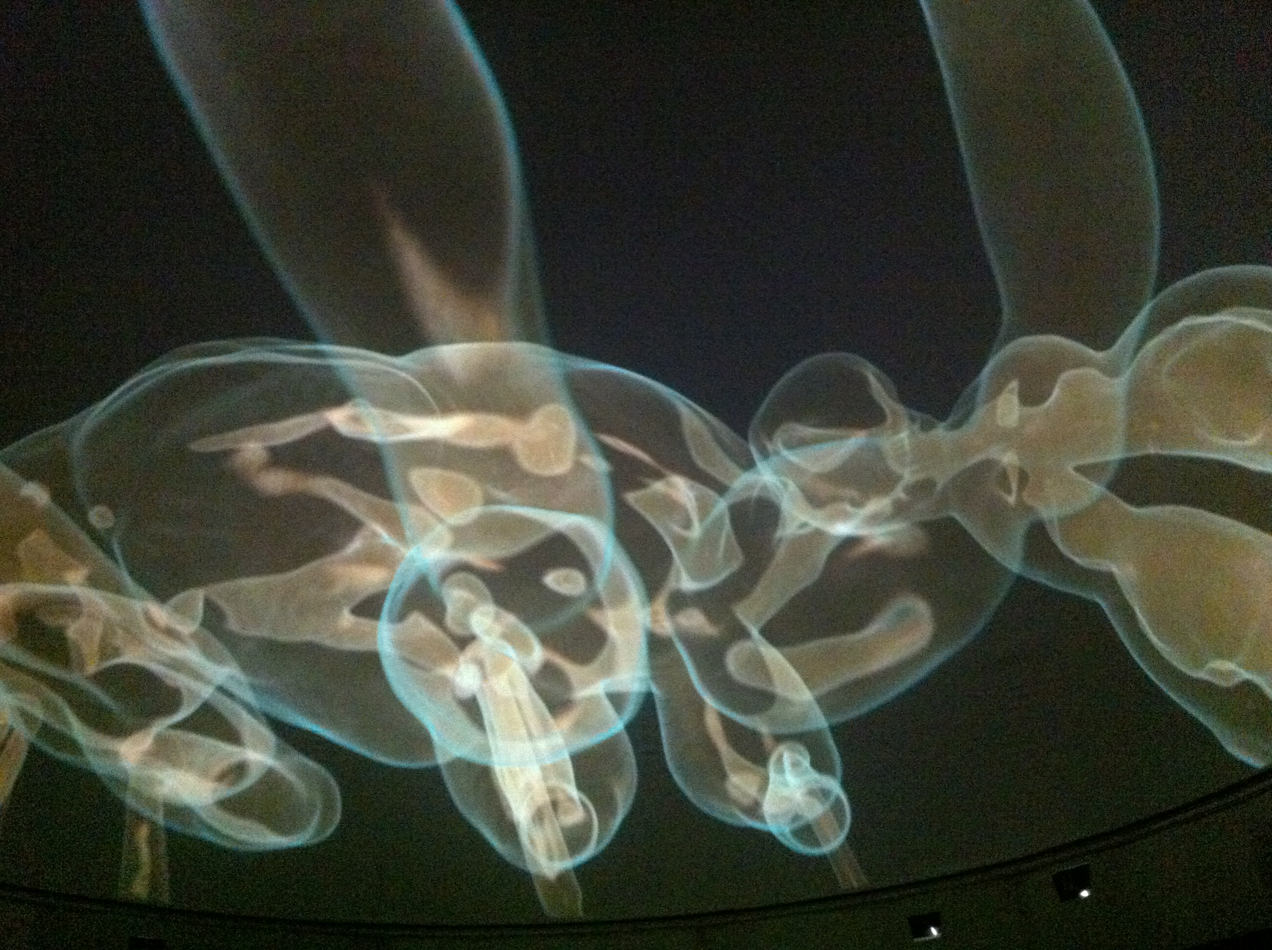
- Rabbit Liver

-

- Ear Bone of Fossil Whale
-

- Terror Ant

-

- Volume Visualisation Under the Dome. Australian National University, University of Western Sydney

CODE IS ART, DATA ART
Everything starts with the pixel, whatever you display on the screen. The pixels are the building blocks and can be real time visualisation, not pre-rendered animations including interactive 3D Graphics for the web, mobile 3D graphics. Attach a mathematical function to each of the pixels, when you can display a pixel you can do every thing, every pixel on the screen is a mathematical function. Two triangle rendering, uses triangles and GPUts to power pixels and works in the browser. Underground art in Europe, programming and self expression. DemoScene. Mathematically driven visualisations that were synchronised to the music.
DEMOSCENE: an international computer art subculture that specializes in producing demos: small, self-contained computer programs that produce audio-visual presentations. The main goal of a demo is to show off programming, artistic, and musical skills. Demoscene.info – is a worldwide non-commercial network of creative minds involved in the making of so called ‘demos’. Demos are computer generated music clips that show what kind of graphic and sound effects can really be done by using high-end computer hardware to its full potential.
OpenGl: open graphics library that enables you to program graphics, including games Open Graphics Library (OpenGL) is a cross-language, cross-platformapplication programming interface (API) for rendering 2D and 3Dvector graphics. The API is typically used to interact with a graphics processing unit (GPU), to achieve hardware-acceleratedrendering. Silicon Graphics Inc., (SGI) started developing OpenGL in 1991 and released it in January 1992; applications use it extensively in the fields of computer-aided design (CAD), virtual reality, scientific visualization, information visualization, flight simulation, and video games. Since 2006 OpenGL has been managed by the non-profittechnology consortiumKhronos Group.
WebGL: can program graphics on the web. It is a cross-platform, royalty-free web standard for a low-level 3D graphics API based on OpenGL ES, exposed to ECMAScript via the HTML5 Canvas element. Developers familiar with OpenGL ES 2.0 will recognize WebGL as a Shader-based API using GLSL, with constructs that are semantically similar to those of the underlying OpenGL ES API. It stays very close to the OpenGL ES specification, with some concessions made for what developers expect out of memory-managed languages such as JavaScript. WebGL 1.0 exposes the OpenGL ES 2.0 feature set; WebGL 2.0 exposes the OpenGL ES 3.0 API. WebGL brings plugin-free 3D to the web, implemented right into the browser. Major browser vendors Apple (Safari), Google (Chrome), Microsoft (Edge), and Mozilla (Firefox) are members of the WebGL Working Group. Learn WebGL: GLSL Built-in Functions and Variables
WebVR: is an experimental JavaScript API that provides support for virtual reality devices, such as the HTC Vive, Oculus Rift or Google Cardboard, in a web browser. Three.js: is a cross-browserJavaScript library/API used to create and display animated 3D computer graphics in a web browser. Three.js uses WebGL. The source code is hosted in a repository on GitHub.
DISTANCE FIELD: using maths to create mesh using distance field. Raymarching of distance field proved super powerful for creating rich images with complex shapes procedurally and interesting efficient lighting effects in a minimal amount of code. Not only the actual content creation code modeling was small, but the actual renderer itself, the whole technical setup to sinthetize images was ridiculously compact comparing to a mesh based rasterizer or raytracer. So, the exercise became really fruitful and I produced 5 images in 2008 alone that I presented to the “4 kilobyte Procedural Image” category of different demo partys across Europe. Those images where created in the many cores of the CPU in a tile based manner.
Ray Marching and Singed Distance Functions with Jamie Wong FRAGMENT SHADER: is the Shader stage that will process a Fragment generated by the Rasterization into a set of colors and a single depth value. The fragment shader is the OpenGL pipeline stage after a primitive is rasterized. For each sample of the pixels covered by a primitive, a “fragment” is generated. Each fragment has a Window Space position, a few other values, and it contains all of the interpolated per-vertex output values from the last Vertex Processing stage. The output of a fragment shader is a depth value, a possible stencil value (unmodified by the fragment shader), and zero or more color values to be potentially written to the buffers in the current frame buffers. Fragment shaders take a single fragment as input and produce a single fragment as output.
Some examples jotted down quickly – accuracy not guaranteed, give the general idea. Functions such as mix, smooth step, sin and time can be combine as you go.
Doing Two Triangle rendering and parallel compute, draw 2 triangles covering the entire screen area and involve a pixel shader, an openGL, WebGL
SCIENCE is CHANGING
Science is changing, four paradigms of science:

Experimental – description of natural phenomena. Measurements as in the renaissance era, look at the sky and see what was gong on and develop a theory base on observations. Theoretical – Newton’s Law, Maxwell’s Equations. Start with a theory and then make observations to test the theory, an hypothesis and then test to see if it is true base on observations about 100 years ago. Computational – simulation of complex phenomena. Large, high performance, parallel machines that can do big number crunching, taking the theory and turn it into a model and develop a mathematical model that encapsulated the theory. Run the program, generating data that would inform the theory and model, about 20 years ago. The physicists, computer and visualisation expert working together developing a theory, building a model, implementing it, running the computations to generate data and the output can be visualise which then informs both the model and the theory. The computations and visualisation of the data informs both the model and theory. Data-Intensive – must move from data to information to knowledge. Data mining, taking a lot of data and run an algorithm or some kind of artificial intelligence and then helps to develop a theory or model based on the data.

Petabyte is a multiple of the unit byte for digital information. The prefix peta indicates the fifth power of 1000 and means 1015 in the International System of Units (SI), and therefore 1 petabyte is one quadrillion (short scale) bytes, or 1 billiard (long scale) bytes. The unit symbol for the petabyte is PB. 1 PB = 1000000000000000B = 1015bytes = 1000terabytes. A related unit, the pebibyte (PiB), using a binary prefix, is equal to 10245 bytes, which is more than 12% greater (250 bytes = 1125899906842624bytes). Why does visualisation matter? Need visualisation of data sets otherwise cannot make sense of it. Problems storing the data that they are dealing with. 100000 computer nodes in a one super computer and each node will be able to computer at 125 petabytes per second. The computation is in the chip, each of the nodes while have memory, when write out to memory it will drop own to 4 and 1/2 petabytes per second of memory bandwidth and will already be losing data from the register file of the CPU to the memory bank in the ram. Already cannot visualise some of the data that is being computed. On node visualisation v off node visualisation. All the nodes are interconnected, the interconnect, very high speed network and the interconnect data rate is 24 TB per sec. Lose more when sending data across nodes, off node visualisation. To write the data to disk, drops again. Going from 125 PB to 1.4 TB of data bandwith. NATIONAL INSTITUTE of STANDARDS and TECHNOLOGY NIST ATOMIC CLOCK NIST-F1 is a cesium fountain clock, a type of atomic clock, in the National Institute of Standards and Technology (NIST) in Boulder, Colorado, and serves as the United States’ primary time and frequency standard. The clock took less than four years to test and build, and was developed by Steve Jefferts and Dawn Meekhof of the Time and Frequency Division of NIST’s Physical Measurement Laboratory.
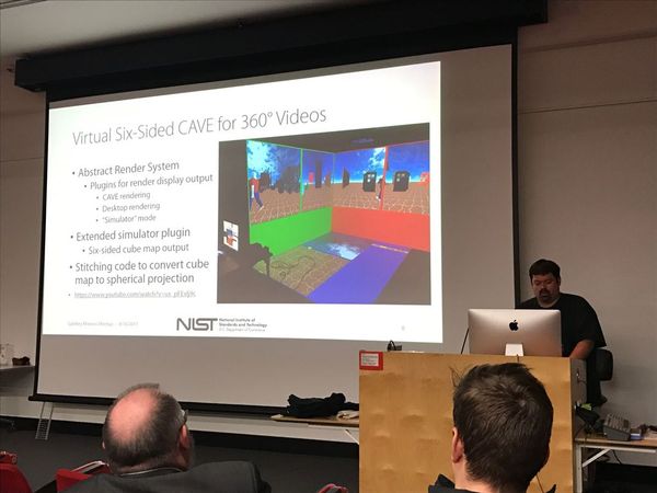
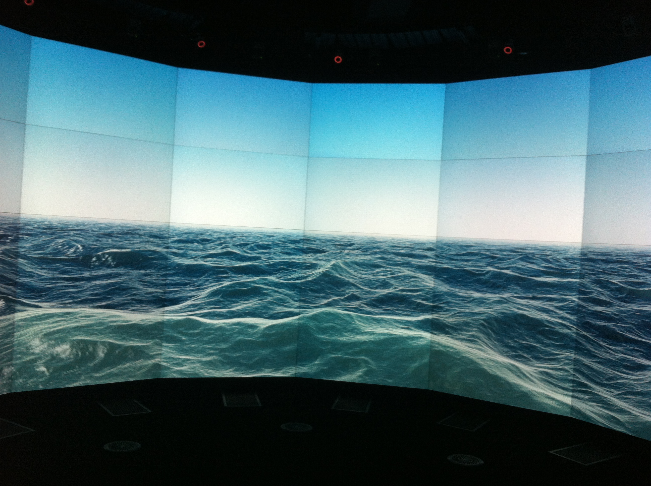
Also has US copy kilogram, last si unit, system of units, that is tied to a physical object. Standard Reference Material National Metrology The science of improving meansurement and how accurate it is. Metrology, as defined by the International Bureau of Weights and Measures (BIPM), is “the science of measurement, embracing both experimental and theoretical determinations at any level of uncertainty in any field of science and technology”. It establishes a common understanding of units, crucial in linking human activities APPLIED and COMPUTATION MATHEMATICS DIVISION  HIGH PERFORMANCE COMPUTING and VISUALISATION, develop simulation codes for visualisations including simulation and experiments. Processes data fro one source and taking to another source so it can be visualised. There is a cave, which is a three screen cave with two walls and a floor. Stand in a corner and almost a 180º emersion. Take the three sides, then another three sides and stick together for 360º video, virtual 6 sided cave. Concrete, second largest material used in the world behind water with the main ingredient being sand. There is little scientific knowledge about how concrete works. Last time 15 million hours were used on the computer and ran the model 4 times. Using a numerical model, giving the scientists the opportunity to validate the experiments. Using visualisation to see what is happening.
  RHEOMETER is a laboratory device used to measure the way in which a liquid, suspension or slurry flows in response to applied forces. It is used for those fluids which cannot be defined by a single value of viscosity and therefore require more parameters to be set and measured than is the case for a viscometer. It measures the rheology of the fluid.
NIST Team Awarded Millions of Supercomputing Hours, Aims for ‘Concrete Results’
Supercomputer Simulations Help Lay Foundation for Better, Greener Concrete
Multimedia for The Visualization of High Performance Concrete
NIST team wins 80M hours of supercomputer time for concrete rheometer study
Visualising a Theory of Everything 
MEL and PYTHON scripting
my assessment and a collection of notes
PYTHON UV LAYOUT TOOL SCRIPT


PYTHON SCRIPTING – Programming 2
- Shells should only be generated along the U parameter
- This tool will layout UVs so that there are no-overlaps
- It must have a user friendly UI
What is causing the problem: brief description of the pipeline issue, a paragraph describing the problem I have to solve and diagrams can be included. What actions can be done to manually solve the problem: research done to find a solution, a few paragraphs listing any research done to find a solution and diagrams can be included. Propose a solution designed to overcome the issues at hand: design of proposed solution, outline using paragraphs, dot point, diagrams and/or images to describe how this custom tool will look and work. A tool which is going to put each face/shell of a polygon model or models into its own UV tile. I needed to revisit Maya’s UV Texture Editor to see how this could work. The UV layout tool is used to apply colours, details and textures from a 2D image to the surface of the 3D model. 3D is based on XYZ, showing where the object is located in 3D space while texture mapping uses 2D images, with U (horizontal axis) or width and V (vertical) or height surface coordinates that shows where these points appear on the 3D surface and how the texture is applied.
For this tool the shells have already been created. The 3D surface to broken up into segments or shells which are groups of UV points with interconnecting lines that are used to created the best possible shape for texturing. The Shell’s seams, where the textures will be jointed, need to be positioned to minimise stretching and warping when applying the 2D images to the 3D surface.  The UV layout tool’s default is to fit the 3D object’s shells within the 0 to 1 coordinates of the grid or tile. This may or may not be the best layout position for the image resolution on the 3D object. It is not necessarily a matter of extending beyond these coordinates as the textures will appear to repeat, loop or wrap. The UV layout grid can be extended in either the U or V creating more tiles, with more UV regions of the same 0 to 1 scale for texturing. This will increase the resolution of the textures or how much of the object’s surface the texture will cover per tile. This tool will apply one shell per texture tile on the UV layout grid in the U direction, allowing for high resolution texturing. There is to be no overlapping which would cause repeating on corresponding vertices.

images from autodesk and area.autodesk.com/tutorials/part_1_multi_tile_uv_mapping
The UV layout grid can be extended in either the U or V creating more tiles, with more UV regions of the same 0 to 1 scale for texturing. This will increase the resolution of the textures or how much of the object’s surface the texture will cover per tile. This tool will apply one shell per texture tile on the UV layout grid in the U direction, allowing for high resolution texturing. There is to be no overlapping which would cause repeating on corresponding vertices. During my research some ideas have come up that I need to consider: Selection – will the user select one or multiple 3D objects at a time and how will they be selected? How will the shells be selected and layed out in the UV Texture editor? Select a single UV and tell Maya to select the shell boarder to grab a single shell and move it to the next tile across or will the whole object be selected. Tiles – will the UV shells be positioned to lie within a user-defined number of tiles or will the number of shells determine how many gird tiles there will be? History – mesh with history may revert to old UV’s? Shells – need to work out how many shells make up the selected models then to be able to put each shell into sequential tiles. Layout – the position of each shell in the tile along the U axis. Shape, Size and Scale – to roughly correlate to each other and the faces of the polymodel, unless want more or less detail or maximise the resolution by filling the image area or UV tile as much as possible. When unfolding multiple shells, do they need a consistent size or will the shell fill the 0 to 1 texture space, Overlapping – smooth UV tool which smooths out the overlapping with Unfold untangling UV’s while attempting to match the shape of the 3D surface. Positioning – in regions other than the default 0 to 1 tile, Scale Mode affects the way shells are arranged on the grid with None arranging the shells to fit within a the specified number of tiles. Uniform arranges the shells to fit within only the number of tiles that are needed. Nearest Region positions the UV shells to lie within the nearest tile. What if I want the shells in the exact same UV position of the tiles, same UV coordinating space on a different tile? Empty Region – around the outside perimeter, especially if the shell’s UVs boarders the tiles edge, empty region (4 to 6 pixels), UV boarders from the tile edge – script 5% scale reduction. Unfold – constraint to none will unfold in both U & V. Do the shells have a consistent size or are they filling the 0 to 1 texture tile. Scale Factor. Uniform scale, the shell to fit the 0 to 1 texture space without changing the aspect ratio and is the default. Inside the UV range in each tile and no crossing of boarders. Normals – how to flip shells that have normals pointing in opposite directions. Not sure if this relates to the blue and red colours for the shells. At this point I went looking in the Maya Help Files to find Python Commands that could be used in the UV Layout Tool script and how they might be used. To start with it was overwhelming, then bit by bit there were some that looked like they could work which started me thinking of possibilities for scripting solutions.
I have listed them below. polyEvaluate command Returns the required counts on the specified objects. Flag: shell(s) returns the number of shells shells (disconnected pieces) as an int polyEditUV Command edits uvs on polygonal objects. When used with the query flag, it returns the uv values associated with the specified components. relative(r)Specifies whether this command is editing the values relative to the currently existing values. Default is true; uValue(u)Specifies the value, in the u direction – absolute if relative flag is false.. vValue(v)Specifies the value, in the v direction – absolute if relative flag is false.. rotation(rot)Specifies whether this command is editing the values with rotation values scale(s)Specifies whether this command is editing the values with scale values pivotU(pu)Specifies the pivot value, in the u direction, about which the scale or rotate is to be performed. pivotV(pv)Specifies the pivot value, in the v direction, about which the scale or rotate is to be performed. scaleU(su)Specifies the scale value in the u direction. scaleV(sv) floatSpecifies the scale value in the v direction. angle(a)Specifies the angle value (in degrees) that the uv values are to be rotated by. uvSetName(uvs) stringSpecifies the name of the uv set to edit uvs on. If not specified will use the current uv set if it exists. polyEditUV Shell Command edits uv shells on polygonal objects. When used with the query flag, it returns the transformation values associated with the specified components. uValue(u) Specifies the value, in the u direction – absolute if relative flag is false.. vValue(v) Specifies the value, in the v direction – absolute if relative flag is false.. polyFlipUV Flip (mirror) the UVs (in texture space) of input polyFaces, about either the U or V axis.. flipType(ft)Flip along U or V direction. 0 Horizontal 1Vertical, Default is 0. local(l)Flips in the local space of the input faces. Default is on. polySetToFaceNormal This command takes selected polygonal vertices or vertex-faces and changes their normals. If the option userNormal is used, the new normal values will be the face normals around the vertices/vertex-faces. Otherwise the new normal values will be default values according to the internal calculation. unfold iterations(i)Maximum number of iterations for each connected UV piece. stoppingThreshold(ss)Minimum distortion improvement between two steps in %. useScale(us)Adjust the scale or not. scale(s)Ratio between 2d and 3d space. areaWeight(aw)Surface driven importance. 0 treat all faces equal. 1 gives more importance to large ones. untangleUV This command will aid in the creation of non-overlapping regions (i.e. polygons) in texture space by untangling texture UVs. relax(r)Relax all UVs in the shell of the selected UV’s. The relaxation is done by simulating a spring system where each UV edge is treated as a spring. There are a number of different methods characterised by the way the UV edges are weighted in the spring system. These weightings are determined by STRING. Valid values for STRING are: uniform – every edge is weighted the same. This is the fastest method. inverse_length – every edge weight is inversely proportional to it’s world space length. inverse_sqrt_length – every edge weight is inversely proportional the the square root of it’s world space length. harmonic – this weighting can yield near optimal results in matching the UV’s with the geometry, but can also take a long time. relaxTolerance(rt)This sets the tolerance which is used to determine when the relaxation process can stop. Smaller tolerances yield better results but can take much longer. maxRelaxIterations(mri)The relaxation process is an iterative algorithm. Using this flag will put an upper limit on the number of iterations that will be performed. polyLayoutUV Move UVs in the texture plane to avoid overlaps. polyMultiLayoutUV place the UVs of the selected polygonal objects so that they do not overlap. layout(l)How to move the UV pieces, after cuts are applied: 0 No move is applied. 1 Layout the pieces along the U axis. 2 Layout the pieces in a square shape. 3 Layout the pieces in grids. 4 Layout the pieces in nearest regions. gridU(gu)The U size of the grids. gridV(gv)The V size of the grids. rotateForBestFit(rbf) How to rotate the pieces, before move: 0 No rotation is applied. 1 Only allow 90 degree rotations. 2 Allow free rotations. Scale(sc)How to scale the pieces, after move: 0 No scale is applied. 1 Uniform scale to fit in unit square. 2 Non proportional scale to fit in unit square. layoutMethod(lm)0 Block Stacking.1 Shape Stacking. offsetU(ou)Offset the layout in the U direction by the given value. offsetV(ov)Offset the layout in the V direction by the given value. sizeU(su)Scale the layout in the U direction by the given value. sizeV(sv)Scale the layout in the V direction by the given value. prescale(psc)Prescale the shell before laying it out. 0 No scale is applied. 1 Object space scaling applied. 2 World space scaling applied. flipReversed(fr)If this flag is turned on, the reversed UV pieces are fliped. percentageSpace(ps)When layout is set to square, this value is a percentage of the texture area which is added around each UV piece. It can be used to ensure each UV piece uses different pixels in the texture. Maximum value is 5 percent. uvSetName(uvs)string Specifies the name of the uv set to edit uvs on. If not specified will use the current uv set if it exists. delete constructionHistory(ch)Remove the construction history on the objects specified or selected. textureWindow This command is used to create a UV Editor and to query or edit the texture editor settings. len(s) Return the length (the number of items) of an object. The argument may be a sequence (such as a string, bytes, tuple, list, or range) or a collection (such as a dictionary, set, or frozen set). All these commands became a bit overwhelming, really need some feedback and to look at the practical side of how they might work and could be applied to the script. The script would start with these ideas:
- The user selects the UV Mapped model or models in the Maya viewport which returns the number of shells in the selection to the script.
- The number of shells will determine how many UV tiles there will be along the U axis.
- The UV Texture Editor’s settings and coordinates including the number of tiles to be build into the script and determined by the number of shells.
- Each shell to be scaled to fit the UV tile , unwrapped with consideration to preserving the ratio of the shape.
- Open the UV texture editor when putting each shell into the tile so the user can see and access the UV texture editor’s.
On further reading of the python commands I would start the script by considering the following ones: polyEvaluate: can return the number of shells as an int polyEditUV: edits UV on polygonal objects. The query flag returns the uv values associated with the specified components. Also has scale(s) which specifies whether this command is editing the values with scale values. polyEditUV Shell: edits uv shells on polygonal objects. When used with the query flag, it returns the transformation values associated with the specified components. untangles: non-overlapping regions in texture space. Uniform – every edge is weighted the same. polyMultiLayoutUV: places UV’s of the selected polygonal objects so they do not overlap. Layout the pieces in the U axis, with the option for not rotation, scale to uniform to fit the unit saucer, flip reversed so the reversed UV pieces are flipped. delete: has a construction history for objects specified or selected. The suggested UI window below with the user to follow the yes or no options. WEEKLY TASKS
- Who is the creator of Python?
The creator of Pyton is the Dutch man, Guido van Rossum, developed in the late eighties and early nineties at the National Institute for Mathematics and Computer Science in the Netherlands and being first released in 1991. 2. How did Python get its name? Guido van Possum named the Python language after the BBC comedy show “Monty Python’s Flying Circus”. 3Name some of benefits of the Python language? Some of the benefits of the Python language are that it is a simple and minimalistic language, easy to read and use, with few keywords and a simple structure with clearly defined syntax rather than the syntax and structure of some other languages. A free and open source language, it can be copied and modified and is based on the concept of a community which shares knowledge. Python is portable, translating into the native language of the computer thus working on many platforms and using the same interface, platform independent . It is also referred to as a ‘Glue’ language meaning it can be integrated with other languages such as C, C++ and Java. DYNAMICALLY TYPED LANGUAGE, python works out the data type as opposed to strongly typed languages that require the data type to be specified. An example would be when programming languages represent data types such as integers, in dynamically typed languages this does not need to be specified e.g. x = 10, while strongly typed languages do need to specify the date type in the script e.g. int x = 10, before declaring the variable. Python works out that 10 is an integer. WHITE SPACE is used to surround and create boundaries, using empty characters or spacing to create the boundaries that surrounds code, delimiter white space is created with tabs or a series of spaces. It denotes and controls the block structure with significant spacing and indentation as opposed to using brackets and curly brackets. When indenting it becomes a child of the previous line and the parent has a colon which creates 4 spaces following it or the use of the tab key. The indentation, instead of curly brackets, is the same level of hierarchy, the same compound statement and the code responds based on these boundaries. If indentation is lost or lines are broken the code will not work as intended. It is visually readable and when the line or statement finishes python assumes there is nothing afterwards without the need to put the semi-colon. INTERPRETED LANGUAGE does not need compilation or converting to binary or machine-code with various flags and options in order to work. It executes instructions directly, runs directly from the source code converting to bytecodes and is translated to the native language of the computer it is running on. As it is complied into machine-friendly formats on the fly it can be slower and less efficient though it is more portable for use on computers, platform independent. Last but not lease python is an OBJECT ORIENTED PROGRAMMING LANGUAGE (OOP) that supports classes, instances and methods which we have not covered yet. It is a way of organising the code as opposed to procedural programming which is like a recipe, a set of instructions to complete a task that is built around procedures or functions or reusable pieces of programs. In object-oriented languages, objects are the centre of the process, building the program around them which combines data and functionality, instead of using them as necessary containers for information. Python has a very powerful but simplistic way of doing OOP, especially when compared to big languages like C++ or Java.’ page Week 2 Task I have 2 variables: number = 87.459998899 version = 3 Using string formatting operators:
- Write the code required to give the number variable a floating-point precision of 3 digits
number = ‘%.3f’ % 87.459998899 >>> print number 87.460 2.Write the code required to give the version variable a padding of ‘0003’ version = ‘%04d’ % 3 >>> print version 0003
>>
Week 3 Task Identify the differences between a List and a Tuple. Lists, like tuples are sequences containing any kind of date with some major differences:
- Lists use square brackets [] and tuples use parenthesis ().
- List are mutable, meaning the data can be modified or changed at anytime after it has been created. Tuples are immutable, meaning after the content or data has been declared or defined it cannot be modified or changed.
If data is separated by a common then python will automatically make it a tuple. It is possible to change the information in a tuple by passing a tuple back into a list, change or modify the list than pass back into a tuple. Week 4 Task
- In around 150 words describe what the Flow of Execution is?
The Flow of Execution is the order in which statements are executed, how conditions are meet. This order is important, not necessarily being from top to bottom as a sequence, referred to as straight-line programming. Statements can be executed using conditionals such as if-statements and loops to create some logic. This controls the execution and creates branching or looping, like a detour back to previous statements, in the Flow of Execution to get the desired result. Boolean logic, true or false values, is a way of making decisions and meeting conditions, resulting in comparing values, asking questions and performing other actions. To have options to make decisions, test and compare data types, Python uses operators allowing a sequence of values to be tested in a tuple. Examples of conditional operators are ==, !=, >, <, >=, <=. Python is adept at keeping track of where it is enabling the script to evaluate truth values for more than one operation. 2. L ist some statements/keywords that are used to control this Flow of Execution? Python provides various tools for flow control including if, elif, else which was covered this week. The If Statement has if as a keyword followed by a text for the truth of a condition, what is going to be tested and is ended with a colon. A condition is being evaluated, if something happens then do this. It is a way of handling conditions, if it is true python prints out the required result and does not go on to the else or elif. The else comes into play if something is false, asking if a condition is meet. If false the script’s branches or streams are followed which is where the flow is directed. There is also the elif giving additional options and the script will continue to check if other tests are true or false. A chain of tests can be created, enabling a multitude of conditions to be tested or evaluated only if the result is False. Conditionals and loops Week 5 Task Some loop types can make use of the options: •Break •Continue Explain what these options do, and why we would use them. Break and continue statements control the ability to alter the flow of execution over the block of code of some loop types. The break statement is used to break out of a loop when a condition is meet, the loop does not continue, does not finish and is stopped from continuing to look through the rest of the loop regardless of weather the following conditions are true or false. The iterations are terminated within the loop containing the break, stopping the execution of the loop immediately, including the else statement. If it is inside a nested loop the break will terminate the innermost loop. The script resumes execution at the next statement, going to the statement after the last statement of the loop. A break statement could be used when some external condition is triggered requiring an exit from the loop. Another example is while loops have the possibility of running infinitely, using a break statement guarantees this will not occur thus preventing the system crashing and losing the script. The continue statement is used to skip the rest of the code inside a loop for the current iteration only when a condition is true. The loop does not terminate but continues on with the next iteration by going back to the top of the loop and starting again. It is returning control to the top of the loop without executing the current iteration, rejecting all the remaining statements in the current iteration of the loop and moving control back to the top of the loop. A continue statement could be used when an external condition, such as input from a user, is triggered, then needing to skip a part of the loop and start the next execution at the beginning of the loop. We have used the break and continue statements with while and for loops. Python break and continue Statement Python break, continue and pass Statements Week 6 Task Write an example of a Function based on the following: 1. is named – half_of 2. is able to take any amount of numerical arguments 3. adds all these arguments together 4. after adding them together, it will divide the value by half 5. returns the final value >>> def half_of(*args): number = 0 for arg in args: number += arg total = number / 2 return total >>> half_of(10,10,10) 15
OR def half_of(*args): total = 0.0 for arg in args: total += arg total /= 2 return total
Week 7 Task Research Question: Discover what the following built-ins are used for in Python version 2.7. 1. input() 2. raw_input() The input( ) and raw_input( ) functions are awaiting input, the user to enter something, then taking their input when the enter key is pressed. They are processed the input in different ways, returning different results from the same input. In python 2.x: input( ) evaluates the input, whatever has been put into it. It is taking the input and performing and eval(), getting the raw input, sending it to eval and then returning the result. input( ) 3 * 4 **5 3072 Expects a syntactically correct python statement and attempts to understand the data entered by the user. If hello world is entered it shows an error, needs to be ‘hello world’ and returns a string. >>> input( ) hello world Traceback (most recent call last): File “<pyshell#2>”, line 1, in <module> input( ) File “<string>”, line 1 hello world ^ SyntaxError: unexpected EOF while parsing >>> input( ) ‘hello world’ ‘hello world’ >>> raw_input( ) takes exactly what the user has typed and passes it back as a string. All it considers is that the entered data will be a string whether it is a string or anything, returning a string. Returning the input in an unprocessed form. raw_input( ) 3 * 4 **5 ‘3 * 4 **5’ Because of how input( ) works it has been considered a security risk, possible source of bugs and confusing. In python 3 the original input( ) has been scrapped and the function previously known as raw_input( ) is now input( ). You can manually do what was the previous input( ), by using eval(input()) if you want the old functionality. python 2.x python3.x raw_input( ) ———-> input( ) input( ) ———-> eval(input( )) ?or eval(raw_input(prompt))?
TEST – multiple choice answers
Question 1: What would the statement “ring ‘%.2f’ % 123.456” print out? Question 2: Which of the following examples is the valid way to write a function in Python? Question 3: Which of the following examples is a valid Python if statement? Question 4: What keyword would you use to add an alternative condition to an if statement? Question 5: What symbol can be used to comment out a single line of code in Python? Question 6: Which one of the following examples would be used to check the type of data that variable “x” is linked to? Question 7: Which of the following statements is not true about Python? Question 8: In Python what keyword is used to output information to the console Question 9: What symbols can be used in pairs to comment out multiple lines of code? Question 10: What would the following function do? def add_values(*args): pass Question 11: Which one of the following statements is valid for creating a tuple in Python? Question 12: Variable “x” is linked to a string value of “10”. Which of the following statements is the correct way to convert the contents of variable “x” to an integer? Question 13: Which one of the following examples provides the most efficient way to add 1 to an existing integer in Python? Question 14: Which one of the following statements is valid for creating a dictionary in Python? Question 15: Whiten of the following examples is the valid way to write a while loop in Python? Question 16: Which one of the following examples is a valid way to pass an integer stored in the variable “number” over to a string in Python? Question 17: Which one of the following examples would you use to print out the third item in the list variable “my_list”? Question 18: Variable “x” is linked to a int value of 20 Which of the following statements is the correct way to convert the contents of variable “x” to a string? Question 19: How would you add the string “DCE3D” to a variable called “name”? Question 20: Which one of the following statements is valid for creating a list in Python?
ADDITIONAL REFERENCES
Python from Scratch: Object Oriented Programming
Strings: Tutorials Point Simple Easy Learning
Variables: dreamsys software Python Scripting Tutorial
Python Programming Derek Banas
SUBLIME TEXT
Text editor for code, markup and prose.
DYNAMICS and MEL EXPRESSIONS
from MEL Scripting for Maya Animators by Mark R. Wilkins and Chris Kazmier
To find out where Maya is looking for your scripts is to type into the script editor:
internalVar -userScriptDir;
PARABOLOID: 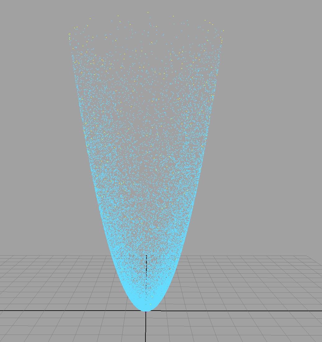 vector $pos = particleShape1.position;//creates a vector variable called $pos and sets it s value to the current particle’s position float $posY = ($pos.x*$pos.x) + ($pos.z)*($pos.z);//new floating-point variable particleShape1.position = <<$pos.x, $posY, $pos.z>>;//assemble the position vector again vector $vel = particleShape1.velocity;//the initial velocity takes a frame to die and solve this particleShape1.velocity = <<$vel.x, 0, $vel.z>>;
MEL SCRIPTING
An interesting article in iiNet’s September 2015 eNewsletter: Should students learn how to code? To rename joints automatically, perfect task for a MEL script
for($each in ls -sl) rename $each substitute "Left" $each "Right";
Can change multiple IK handles’ priority by selecting the IK handles and entering this MEL command. The autoPriority flag automatically prioritise the. selected IK handles based on their position in the hierarchy.
ikHandle -edit -autoPriority;
Programming for 3D: Studio 1 – MEL Report: Top-Down Development Process
Top Down Development Process for MEL Project Top down development is the process of designing a script from scratch. My idea is for the user is be able to enter a predetermined number and have the timeline playhead move that number of frames either forward or backwards from the current playhead position.
- identify the current position of the playhead
- enter a value to move the playhead either forward or backwards
- choose between forward or backwards when moving the playhead
- calculate the offset timeline position from the current playhead position
- move the playhead to the new current time position
- store this as the current time
- update as the new current playhead position
- enter another number to move the new playhead position either forwards or backwards
- create a display window for the user to enter the number for either forward or backwards
- include in this display the option to select either forwards or backwards for the amount of frames entered
MEL Project
 /*=================================================== Script Name: tol_scriptFrameIncrimentMover.mel Vincent Rossini & Therese O’Leary 291014 —————————————————— This script moves the timeline playhead forward or backwards from the current playhead position by the number of frames entered by the user through the displayed window =====================================================*/ //backend proc frameMover(string $direction)//the proc called frameMover requires a string as its arguement and the string is called $direction { float $offset = `floatField -query -value offsetFrame`;//the value entered by the user is queried //offsetFrame being + or – of the playhead position and the offset if($direction == “forward”)//the direction selected is equel to forward then the first part will happen, if false then the else part will happen { float $selectedFrame = `currentTime -q`; //will query the selected frame of the current position of the playhead //pass the information to the named variable float $offsetFrame = ($offset + $selectedFrame);//will add the offset value to the frame of the playhead position //passes the value into the named variable currentTime $offsetFrame;//the new current playhead position } else//when the direction is not forward then it will be backwards { float $selectedFrame = `currentTime -q`;//will query the selecte frame at the current time float $offsetFrame = ($selectedFrame – $offset);//will subtract the offset value from the current playhead position currentTime ($offsetFrame);//reads the new playhead position } } //frontend if (`window -exists myWin`)//checks if the myWin exists { deleteUI -window myWin;//if true delete the existing myWin window } window -title “Frame Incriment”//flag for the name of the window as displayed -minimizeButton false//turns the window’s minimize button off -maximizeButton false//turns the window’s maximize button off -sizeable true//makes the window interactively resizable myWin; //use window command to create a window with a title called Frame Increment rowLayout -numberOfColumns 3;//defines the layout of controls displayed in the window, three spaces across in a row symbolButton -image “timeprev” -command “frameMover(\”backward\”)”;//the backwards arrow symbol from maya database in first space of row //new idea here with string excape characters, two strings //user presses the button the command flat to proc called frameMover to go backwards the value entered in the floatfield floatField -value 10 -precision 1 -width 130 offsetFrame;//ability to enter numbers with one decimal place, has a default number and size, name symbolButton -image “timenext” -command “frameMover(\”forward\”)”;//the forward arrow symbol from maya database in third space of row //as for backwards only forward this time showWindow myWin;//command to display the window in Maya interface
WEEKLY TASKS
Week 6 Task Based on the class exercise of the Average Position script and the following reading. In around 50-100 words, describe what Top-Down Design is?
Top-Down Design is the process of designing a script by breaking it down into steps, a list, a set of instructions that will tell Maya what to do and in what order. Like using a recipe to make a cake.
Initially work out what is the intended outcome, what is the problem the script is going to solve, what does the user do?
Then before writing the code think through the plan, how is it going to work and list the details in the order of the scripts process. When considering how the script is going to work this order is important otherwise it will not work, the list is the order. Would I ice the cake before I baked it in the oven?
When scripting work through the list breaking down the steps further for each instruction or line of code.
The script will run into problems as you go and there will be more than one way to solve the problems. In class we had a script that worked for polys then what if we wanted to for nurbs?
Wilkins, M & Kazmier, C. (2005). Procedures and Functions. In: Cox, T MEL Scripting for MAYA Animators. 2nd ed. San Fransisco, CA: Morgan Kaufmann. 171-174. Week 5 Task In around 50-100 words, explain why you might want to use the Eval command?
The eval command allows the user to execute MEL commands when using valid lines or statements of MEL. It is done when the MEL command is highlighted and Maya runs it as code at runtime.
Before the eval command is used the MEL command entered into the textfield is not being run as MEL. For example, the polyCube requested is not being displayed in the user’s scene. Maya is not running polyCube as code.
The eval command will create the polyCube in the scene thus executing the MEL command polyCube. I am able to construct a valid statement and/or command in a string, run the string as an argument and the result is passed into the string, variable. With the eval command we are now able to execute a string as a MEL command when a valid MEL command is entered into the user’s textfield.
Another thing we did in class: We also run single statements, put them in quotes and the command flag will automatically see the string and do an eval. We used this when we were making our window, this cleared the type entered into the scrollField.
menuItem -label “Clear” -command “scrollField -edit -clear MSScrollField’;
Wilkins, M & Kazmier, C. (2005). Using MEL Commands. In: Cox, T MEL Scripting for MAYA Animators. 2nd ed. San Fransisco, CA: Morgan Kaufmann. 142.
http://download.autodesk.com/us/maya/2010help/Commands/eval.html
Vince’s video
Week 4 Task
Week 3 Task Give a brief description of what each of the following property modes do when working with MEL command flags.
- Create
- Edit
- Query
MEL command flags can be run in different modes using properties which are listed in the command documentation under properties. For example under the Cylinder command, the flags such as radius and spans are listed with the properties of C, Q and E meaning these can be run in Create, Query and Edit modes.
Create: means to create. It is not necessary to specify this in the script because when a MEL command is used to create something the create mode is the default. Maya assumes this, putting it in create mode if I do not specify that I want to edit or query an object. For the command cylinder, when I run it a cylinder is created using the default flag settings. The command documentation list what the default settings are such as a radius of 1. When making a display window with a button, when I type button in the script and run it MEL will make a button. When a MEL command is used to create an object, that MEL command is said to be used in create mode.
Edit: is another mode that I can specify in the script to be able to edit or change something that already exists. Some of the flags belonging to the commands that were used to create can also be run in edit mode to make changes in some way. I could change the default radius or number of spans for the cylinder or the width or label of the button. When doing this I need an argument because it is going to change the value. The argument types are listed in the command documentation eg to edit radius the argument type is linear.
Query: is used to retrieve the values of those attributes that have command-line arguments. When the script is run querying a flag it will go and look for the value that is inside the command and return the value of something that already exists. I may need to query something in order to see what the user typed in, what is inside a field and/or a value used to create something.
In class we used a floatFieldGrp in our script to display the x value part only from the possible options to display the x, y, z in our front end window. Later we were able to use query mode to find out which of these x, y, z display options we had used. For the create cylinder command it is possible to create a cylinder with a radius of 3 and later using the query mode ask the command flag, radius what is this value.
Week 2 Task In around 100 words describe what the purpose of using operator precedence is? You should also include one code example based upon your findings.
Maya follows rules to determine the order of operations, not knowing the order in which an expression will be calculated can and does give wrong results.
Without any operator precedence the following calculation is read from left to right, in the order they appear, returning 30.
10 + 5 * 2 = 30.
When this script is run in Maya it returns a value of 20, because maya is evaluating the multiplication operation first, then the addition. The multiplication has the greater of the precedences or operator precedence.
Using mel’s operator precedence, reference from Maya user guide below, the * will be calculated before the + and now the calculation = 20 with 5 * 2 being calculated first then 10 being added to the result.
To force a calculation to be done first, or override the default it can be done by grouping them using parentheses. Being the first in the order of operator precedence and having the highest precedence.
(10 + 5) * 2 = 30 When operators with the same precedence are encountered in a statement, they are grouped from left to right in the order they appear and evaluated left to right.
Complete Maya Programming: An Extensive Guide to MEL and C++ API, By David Gould, page 90 & 91 of the link.
For example 7 – 1 + 4 = 10 to override this it is possible to do the addition first using parentheses. 7 – (1 +4) = 2 Maya User Guide:
The following shows the order of operator precedence in MEL. Operators on the same row have equal precedence. If a statement has two or more operators with the same precedence, the left-most operator is evaluated first. Unary and assignment operators are right associative; all others are left associative.
 Week 1 Task Based upon this weeks readers, and what you have learned in class. Please anwser the following questions.
- What type of variable would you use to store alpha-numeric charactors in?
String.
- An array’s first index value is always what?
Zero, whatever the data is the first slot is always zero.
- What happens if you redclare a variable name as a different type?
When declaring a variable the space in ram is crated with the data type eg int, when redeclaring a different variable data type because the space in ram was designed as an int and now I may want a float it will redeclare it as ‘invalid redeclaration’. A couple of options to deal with this is to either restart the program or use a different name.
ADDITIONAL REFERENCES
Scripting for Computer Graphics
http://wiki.bk.tudelft.nl/toi-pedia/MEL_-_Interfaces Variables in MEL MEL_GUI Wilkins, M & Kazmier, C. (2005). Procedures and Functions. In: Cox, T MEL Scripting for MAYA Animators. 2nd ed. San Fransisco, CA: Morgan Kaufmann. 171-174. Karmic Hariharan WEB: http://www.melscripting.com – MEL Scripting for Maya Animators by Mark R Wilkins and Chris Kazmier http://www.creativecrash.com/maya/ – Creative Crash http://forums.cgsociety.org – CG Society http://www.autodesk.com/products/alias-products/overview – Alias, Autodesk comp.graphics.apps.alias
MEL SHORT ANSWER EXAMINATION
Question 1 a) What does the acronym MEL stand for? b) Give a brief explanation of one reason to use MEL
Question 2 What is the definition of a variable?
Question 3 Name (4) variable data types found in MEL
Question 4 a) If you wish to store a whole number in a variable, which data type would be used? b) If you wish to store a series of words in a variable, which data type would you use?
Question 5 a) What resource would you use to check the synopsis of a particular MEL command? b) What does the “M” property mean with regard to a command’s flag?
Question 6 a) What is operator precedence? b) Using the Print command and Operator Precedence; fix the statement below to ensure that: 10 + 5 x 10 will equate to 150
Question 7 You want to create a NURBS sphere with a radius of 10 and store the name of the newly created sphere in a string array variable called $ballName, however there are 2 syntax errors in the following MEL statement: string ballName[] = sphere -radius 10; Re-write the statement with the required corrections.
Question 8 a) Name MEL’s primary conditional statement keyword? b) Give a brief description for the purpose of a conditional statement?
Question 9 Give a brief description of what variable scope is?
Question 10 You need to run multiple MEL statements with a single word. a) Name the MEL feature you would use to take care of the above situation? b) Name the button -flag you would use to execute some MEL when your button is pressed?
